Digital Clock (part 3) – Counter and multiplexer

When I started this project back in the spring of 2016 I did not think for a moment that it would take so long to finish it. But the fact is that between whistles and flutes I left it super abandoned. While I was waiting to finish the TFG I was unable to get any project and then this part of the circuit is more complex and until I ordered the PCB to China, it has not worked.

COUNTER

The part of the counter corresponds to the clock's nucleus, since the pulses are counted in cascade to count minutes, tens of minutes, etc. I have based the design on an example of Proteus 7 changing things for my specific project. The most difficult thing at the time was finding the abovementioned counters SN74LS160N. In the case of integrated circuits of the 70's plus the AIDS that give the electronics stores in Madrid, well let's say I had to go through several stores and I did not get anything cheap 74XX chips. First I tried to make one sided PCB, but I was not very skillfull with the acid and many airwires came out, let's say everything was aimed to fail. Obviously, the PCB did not work. Finally I placed and order at JLC PCB.

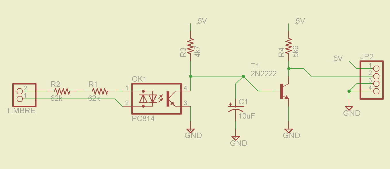
The schematic is the following:

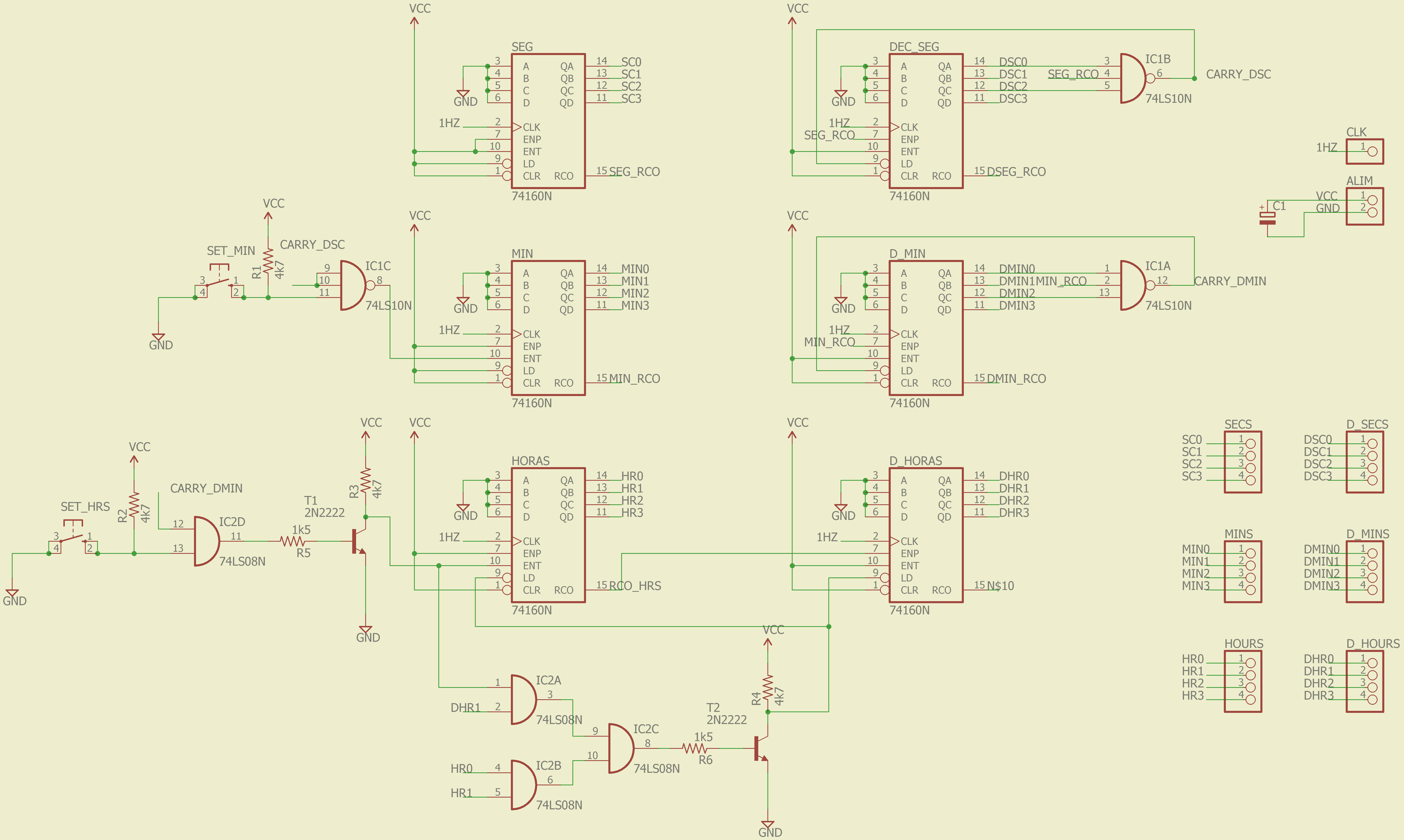
The reason for using AND gates and inverters with a BJT is that when I went to buy the IC's there was only a 74LS10 (3x 3-input NAND) and there were no 4-input ANDs, so I bought a 74LS08 (4x 2-input AND) and I managed with two transistors. Without going into much detail, the count enable of each counter is fed by the overflow of the previous one. Despite being counters with a 4-bit output, being decimals, the overflow occurs automatically in the transition from 9 to 10.

(more…)

Hello World – Blink

In this post I will explain all the steps to launch our Hello World with STM32, a Blink. It is convenient that you have read the previous entries to be able to successfully complete the Blink. We opened the CubeMx and click on New Project. The following screen will appear:

e12There are two tabs: MCU Selector and Board Selector.

(more…)

STM32CubeMX

As I mentioned in the welcome post, I started to mess with the STM32 a year ago, at the time I did not find much info in Spanish, so at the beginning of the summer of 2016 I wrote a tutorial that until now I have not published in the Blog. This Getting started I did for the STM32F103, but let's say the steps for others are similar.

What is cubeMX?

It is an ST software that provides the necessary tools for the generation of project code for the IDE in which you will develop your project (Keil, Eclipse, etc), inclusion of libraries (HAL, GPIO, etc), assignment of roles to the pins of the micro, configuration of clocks, and all other relevant parameters of the micro.

Download CubeMX

http://www.st.com/content/st_com/en/products/development-tools/software-development-tools/stm32-software-development-tools/stm32-configurators-and-code-generators/stm32cubemx.html

We click on the link that will take us to the following page:e0 (more…)

ESP8266 wireless doorbell Part 3: Receiver

Until now, in the previous versions of the ring receiver, the warning device consisted of a ring of 3mm leds and an active buzzer. A friend gave me a pair of led 8×8 monochrome common anode matrices, so I decided to go a step further and play with some animation shown by the matrix.

Deeder_M.jpgdl1250

At the beginning, the driver of the matrix I did with a register shifter 595. It did not convince me much, because nobody frees you from the 8 resistances per row / column. So by doing some research on the network, I found a wonderful integrated, the MAX7219. This multiplexes you 8 anodes and 8 cathodes so you can use it with displays of 7 segments of up to 8 digits, LED arrays, etc. In addition, the maximum intensity per segment is controlled by nothing more than a resistance and the communication interface is by SPI.

IMG-20160824-WA0041

(more…)

ESP8266 wireless doorbell Part 2: Detector

At the time when I designed the first version I broke the coconut by how to detect the buzzer so I could treat it as a 0-off 5V-on signal.  I came up with several ways:

  • Current transformer, using the cable itself that feeds the bell.
  • ACS712 current sensor, which I ended up discarding, because as I calculated then, the current that feeds the bell just reaches 100mA I remember, and the sensor measured 0-30A or -15-15A, a bit useless right?
  • A piezo stuck to the bell housing, this alternative was not tested.
  • Effect Hall, and with this one, I ran out of ideas for a non-invasive sensor, I did not try it either.

Finally I used an AC814 optocoupler with a few 1 / 4W resistors to limit the current to 5mA. Having no higher power resistances, I made calculations, and putting 2 of 62k no dissipated more than 0.25W or Vpico.

See the circuit.

detector

(more…)

Light landing ESP8266

As you could see in the previous entry of the blog light-landing, although it worked fairly well, in certain hours of light, the voltage of the resistive divider that went to the base of the transistor oscillated too much causing the transistor to turn on and off quickly. I put a condenser to eat those oscillations, but obviously, the response became much slower. That is why I considered making a second version. I was doing some tests with Schmitt trigger circuits but I did not agree too much on the result.

IMG_20160516_200823

In May I made a fairly large purchase of components to China where several ESP8266 modules came in several versions: ESP01, ESP07 and nodeMCU (ESP12E). So since the IoT is fashionable, I started to develop the light sensor again to implement it with these chips. The ESP8266 are a pass, and being able to provide WiFi connectivity to your projects is great.

(more…)

Digital Clock (part 2) – Frequency divider

The clocks base their operation on a period of source oscillation. When there were no semiconductors to the clocks, they had to be wound, moved a pendulum or use a crystal oscillator. In this way you got a sustained oscillation which then, in the case of mechanical clocks, was divided into longer times by playing with the gear ratio of a gear train.

clock-mechanic-gona-zonacasio-2013-01

Many of the current clocks use a quartz crystal as source of oscillation, material which has a natural tendency to produce a constant frequency oscillation. In the case of an electronic circuit, quartz can be modeled as a capacitor that is periodically discharged and charged. With the help of auxiliary capacitors and a resistor, an RC oscillator circuit can be achieved at a desired frequency.

Having this clear the following question arises, what base frequency is the most appropriate from which to start?

tim47 (more…)