In this post I will explain all the steps to launch our Hello World with STM32, a Blink. It is convenient that you have read the previous entries to be able to successfully complete the Blink. We opened the CubeMx and click on New Project. The following screen will appear:
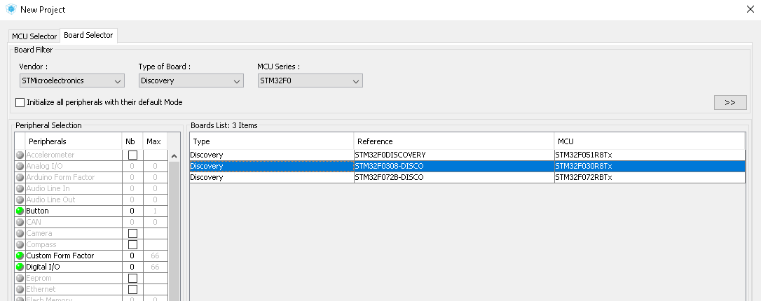
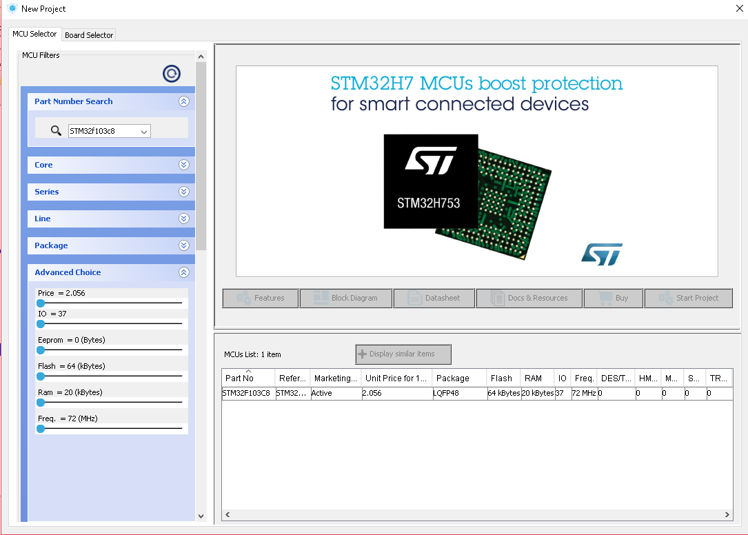 There are two tabs: MCU Selector and Board Selector.
With Board selector we would look for our Discovery F0.
 With MCU Selector we will look for our STM32, either with the help of the filters or by writing in the search engine the reference if we know it.
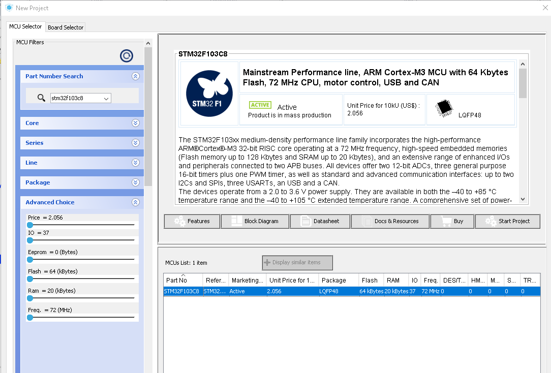 By selecting the MCU Selector our micro, in this case the STM32F103C8 will be available the following options:
- Features: in the big picture it will show us a summary of the micro with its most relevant characteristics (family, memory, GPIOS, etc),
- Block Diagram: A view of the components of the micro.
- Datasheet: We will open in PDF the datasheet.
- Docs & Resources: From here we can download and open the rest of the relevant documentation.
- Buy
- Start Project
By clicking on Start Project we will see the following screen:
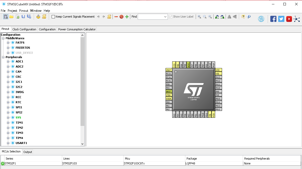
In this screen we will assign the pin of the Led that is integrated in the board to carry out the test. Perhaps someone has already noticed that the default plates come with the blink loaded, however it is the most basic example to explain the configuration of the project.
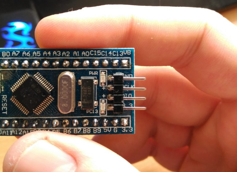 If we look carefully at the board, next to the led we get the name of the physical pin to which it is connected, which we will configure in the CubeMx as GPIO_OUTPUT. Using the Find tool on the toolbar, we look for the name of the pin that appears on the board: PC13. Once selected, it will be shaded intermittently in the drawing of the microphone.
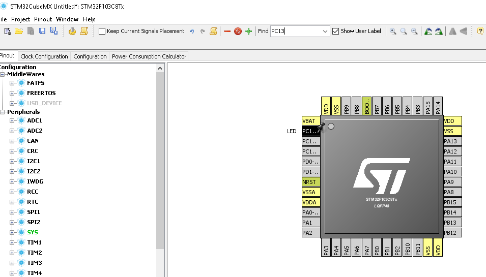 By clicking on the left we will see the dropdown of the possible roles of the micro pin, select GPIO_OUTPUT. The program will color in green the pin indicating that we have assigned a purpose to the pin. If there is an option in Red, it means that there is a role conflict with another functionality that uses that pin. After this, right click on the pin / Set User Label, we write "LED" as seen in previous images. This will be the name that the pin will have by adding "_Pin" to it in code.
We return to the main project screen, and in the top bar Project / Project Settings:
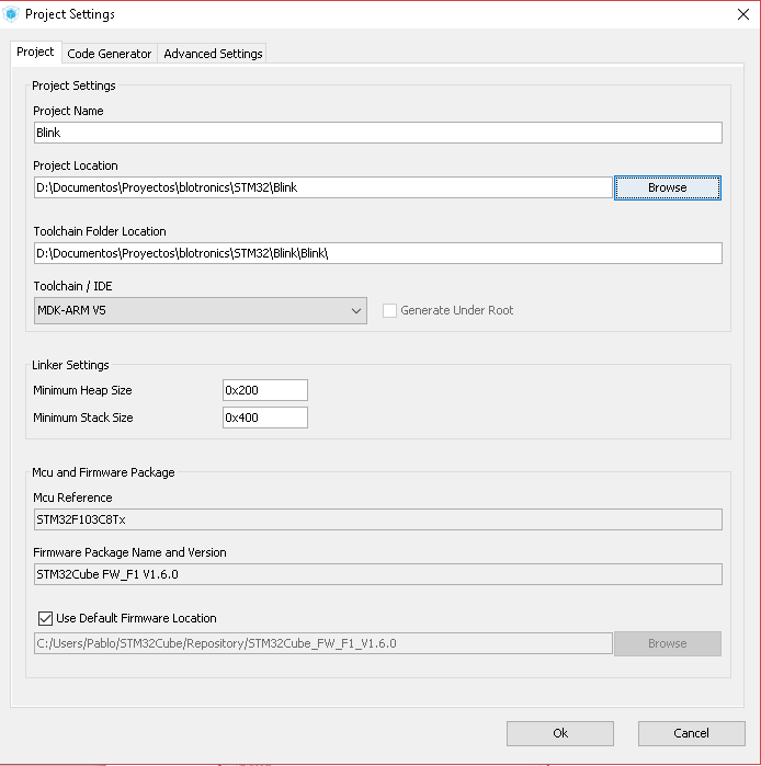 In the part of Toolchan / IDE, select according to the IDE that you have installed, in this case it has been Keil uVision MDK-ARM v5, for the case of Eclipse it would be SW4STM32.
We give Ok and when it finishes the following will come out:
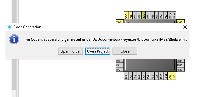 Clicking on Open Project will open the project in uVision.
As you can see, thanks to the CubeMx, we have all the necessary files to start working already configured.
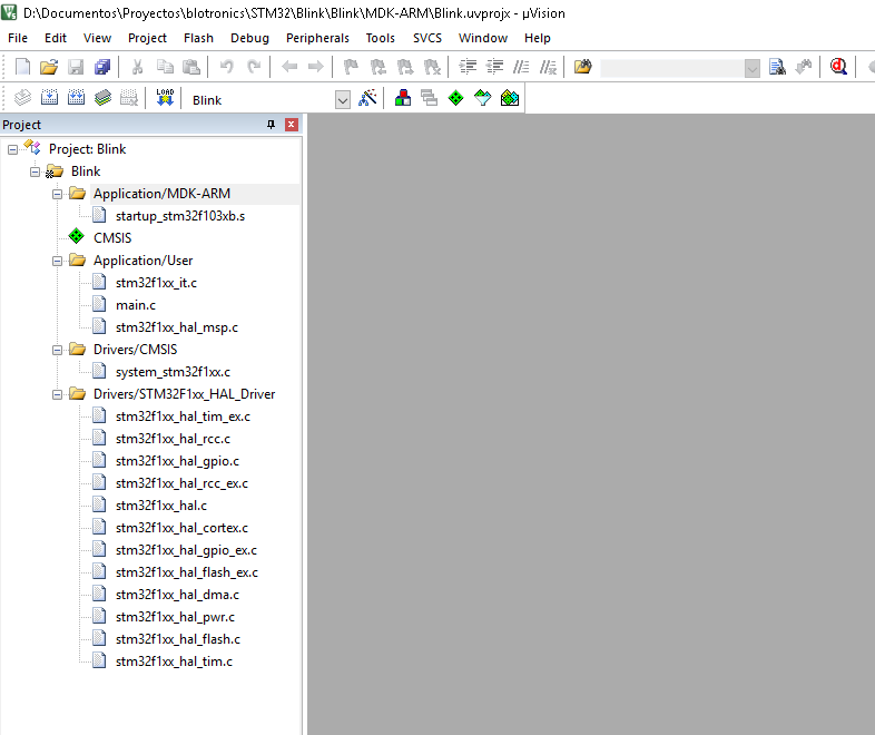 If we browse through the various .c and .h we will find the functions with which to program. In the case of the Blink, in stm32f1xx_hal_gpio.c we will find the possible actions to perform with the GPIO, in this case we will use the function HAL_GPIO_TogglePin.
In the file stm32f1xx_hal.c we will find the other function that we will use HAL_Delay.
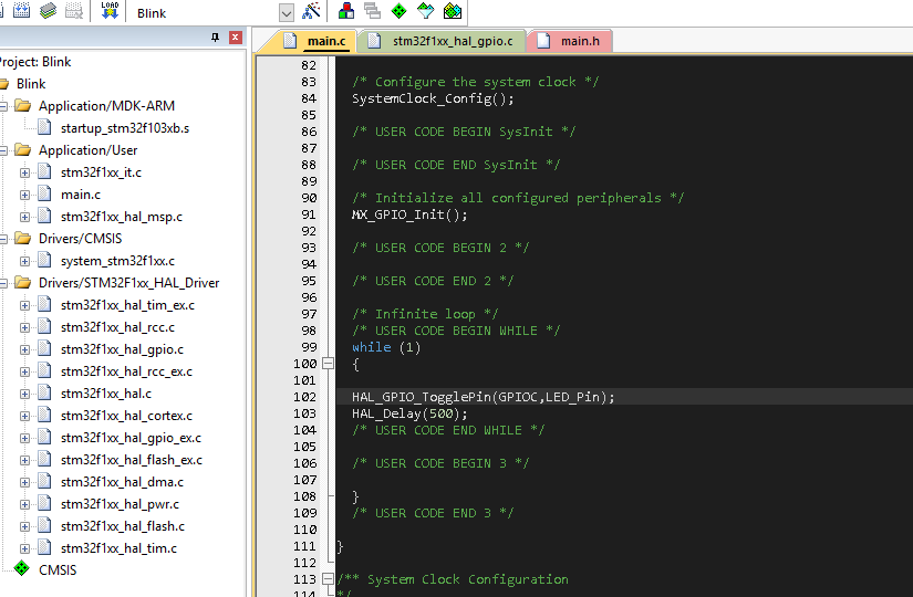 Open main.c and in the while (1) we add the two lines that are seen in the photo. TogglePin has two parameters: the GPIO port (GPIOC) and the specific GPIO (LED_Pin). Delay has only one, the time in milliseconds.
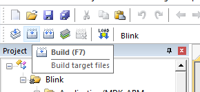
In the menu that is just above the file tree, we give it to build.
 If you have not given an error, then we will load the code on the board using ST-LINK. If you do not have an ST-LINK in the next blog post, I will explain how to load the code using a USB-UART converter.
In the Nucleus and Discovery the ST-LINK is integrated. However you can always buy the ST officer or use alternative routes: my ST-Link is from Aliexpress and it works perfectly.
Before giving Load, next to Build, make sure you have the ST-LINK drivers installed, they are obtained on the ST website:
http://www.st.com/en/development-tools/stsw-link009.html
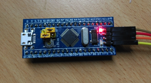
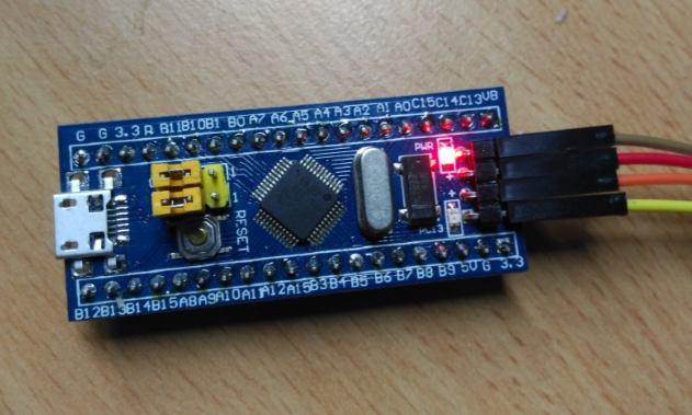
To be able to load our program, for the case of the STM32F103C8T6 board that I am using, it is necessary to put the jumpers that it carries over as it is seen in the photo and to hit the reset button. If you do not do this, uVision will give you an error because it does not detect the micro via ST-LINK.
Once this is done, we give Load, if everything went well, we should see something like that in the uVision Build Output.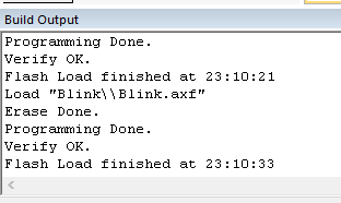
Once the program is loaded, we return the Boot jumper to the 0 position and press the RESET again.
 And voila! Blink!
0 Comments