Until now, in the previous versions of the ring receiver, the warning device consisted of a ring of 3mm leds and an active buzzer. A friend gave me a pair of led 8×8 monochrome common anode matrices, so I decided to go a step further and play with some animation shown by the matrix.
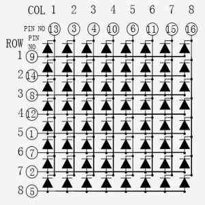
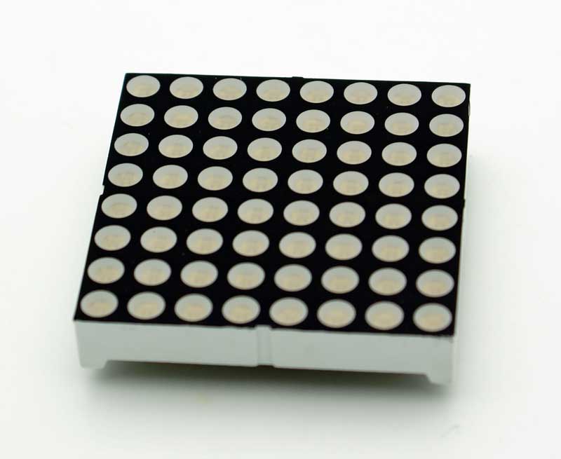
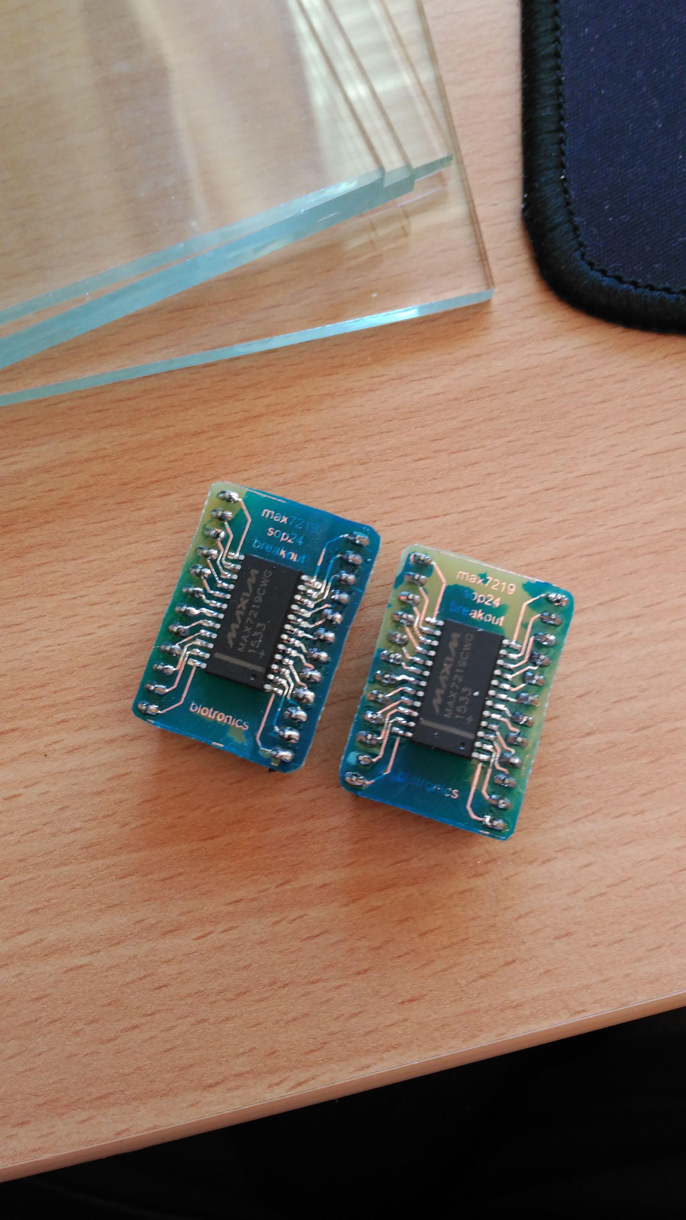
At the beginning, the driver of the matrix I did with a register shifter 595. It did not convince me much, because nobody frees you from the 8 resistances per row / column. So by doing some research on the network, I found a wonderful integrated, the MAX7219. This multiplexes you 8 anodes and 8 cathodes so you can use it with displays of 7 segments of up to 8 digits, LED arrays, etc. In addition, the maximum intensity per segment is controlled by nothing more than a resistance and the communication interface is by SPI.
I ended up finding an Adafruit library (for a change) that by defining an array of 8 bytes, you can define the 8×8 images to be displayed by the matrix, and then send them row by row through SPI through the library's API.
The first tests I did with an Arduino Uno and then I have ported the code to a nodeMCU for tests of connectivity and reception of messages.
I have resorted to the UDP protocol given its simplicity. If you have seen the codes of the light sensor as well as the detector, you will have seen that the UDP commands are sent to a fixed IP. If you have the dhcp activated on your router, which is going to be most likely, I recommend that in the dhcp configuration you reserve the IP in question for the MAC of the device to which these commands go. I know that it is not the most elegant solution, but it has been simple for me.
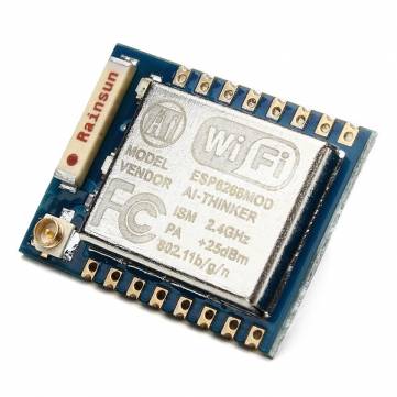
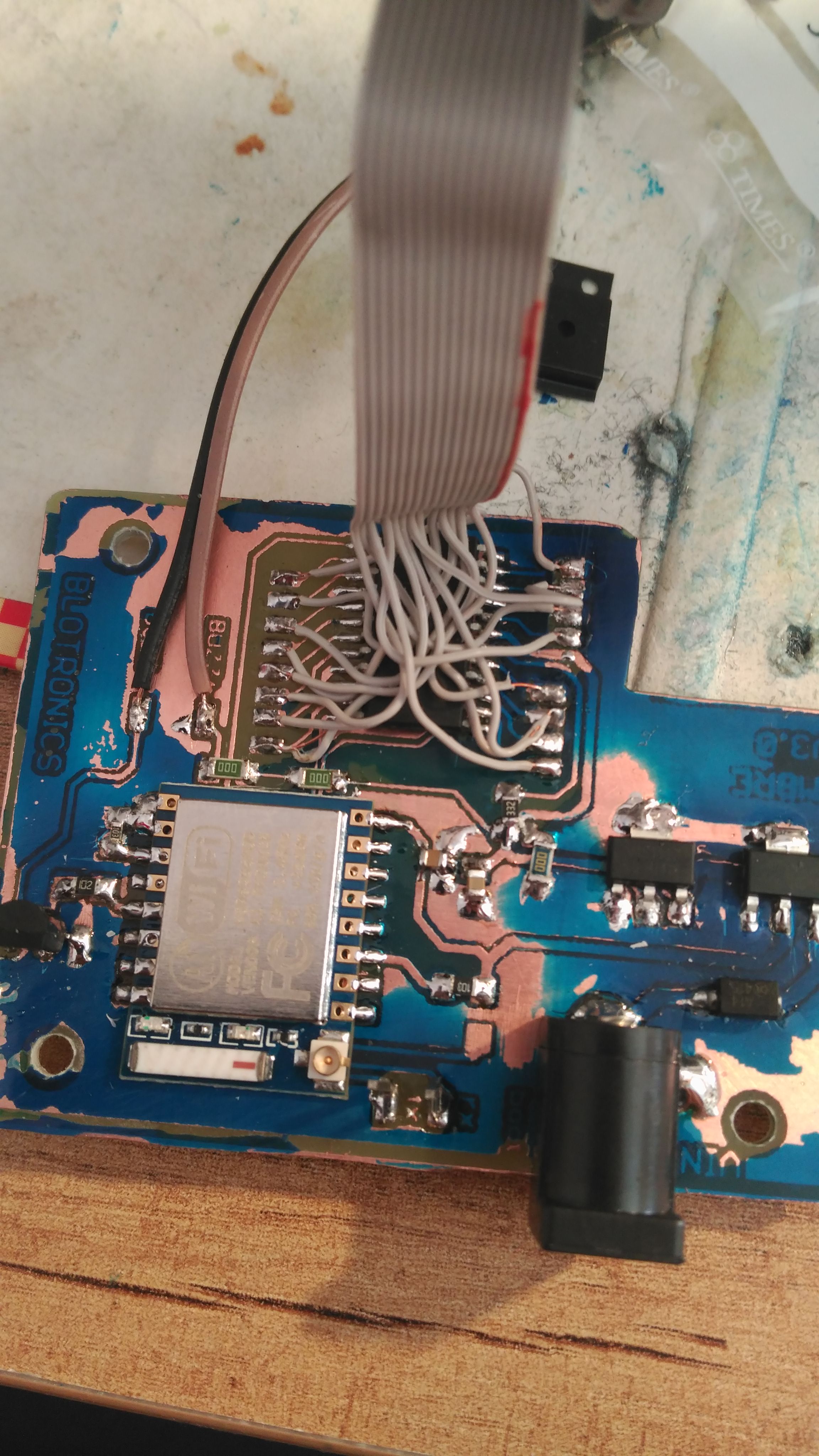
For this module I used ESP07, which is another variant of ESP8266 with accessible and weldable pins. In addition to having the integrated WiFi antenna, it has a UFL connector in case you need more coverage. Given the complexity of the circuit, for this one I have designed and manufactured a plate with mostly SMD components.
I have also tried the method of UV painting to protect the plate, but as you can see I have not taken the time. But hey, the board already has a second version fixing the faults of which is currently mounted, which I'll leave to see how it responds.
 This is the scheme of the circuit:
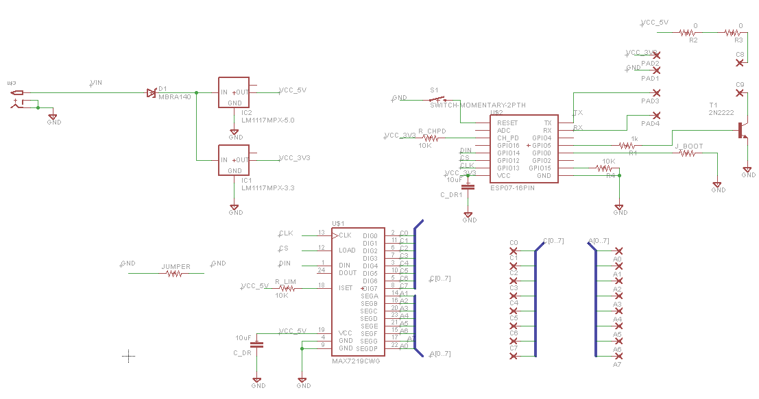
Do you remember that UDP command that I send in the light sensor? You will have asked for what it will do. Well, to differentiate 2 different types of timbre. In my case, I have two doorbells, one on the outside gate and another on the house door, which covers the PIR of the light sensor. So I use the PIR shot to determine where they are ringing the bell (so if the neighbor comes to complain because I am giving love to the amp and the guitar, I can pass directly from it. : P), jokes aside, I think it is useful to differentiate them.
Here you have the code.
and here the final assembly.

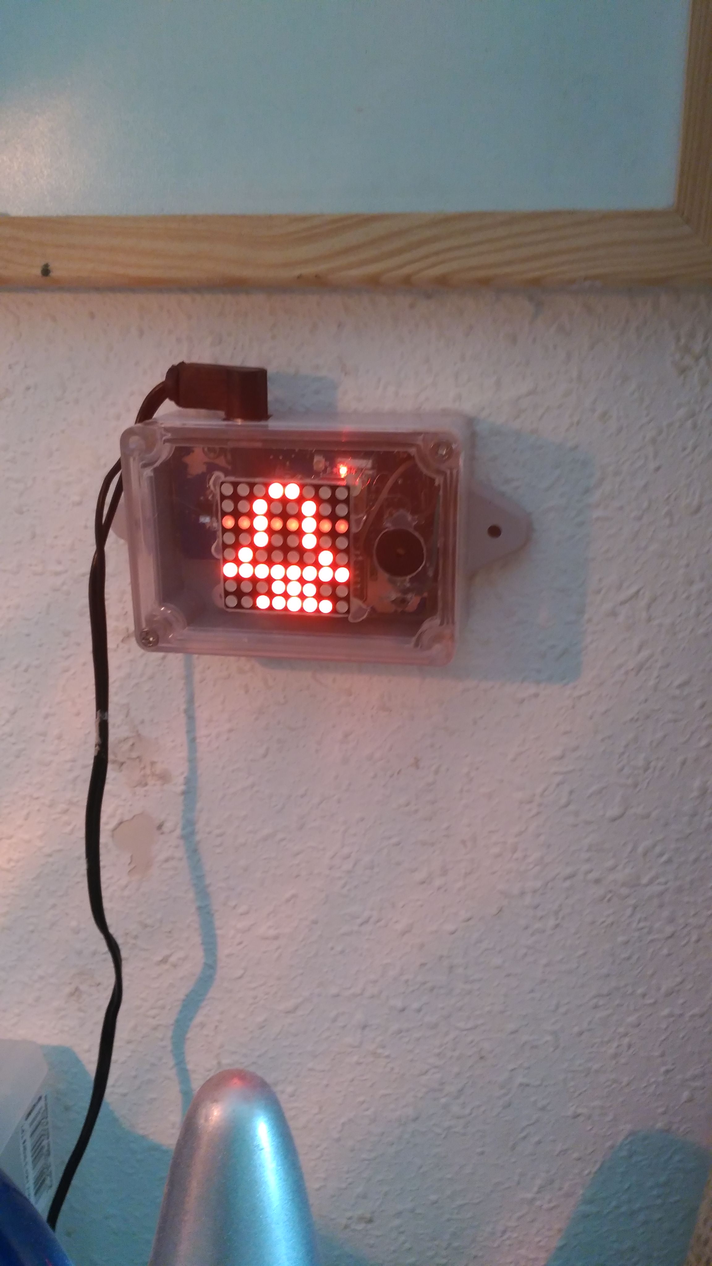
In my instagram account I have videos in which the animation is seen.
https://www.instagram.com/p/BJgmKncgkEC/?taken-by=picatostas
0 Comments