When I started this project back in the spring of 2016 I did not think for a moment that it would take so long to finish it. But the fact is that between whistles and flutes I left it super abandoned. While I was waiting to finish the TFG I was unable to get any project and then this part of the circuit is more complex and until I ordered the PCB to China, it has not worked.
COUNTER
The part of the counter corresponds to the clock's nucleus, since the pulses are counted in cascade to count minutes, tens of minutes, etc. I have based the design on an example of Proteus 7 changing things for my specific project. The most difficult thing at the time was finding the abovementioned counters SN74LS160N. In the case of integrated circuits of the 70's plus the AIDS that give the electronics stores in Madrid, well let's say I had to go through several stores and I did not get anything cheap 74XX chips. First I tried to make one sided PCB, but I was not very skillfull with the acid and many airwires came out, let's say everything was aimed to fail. Obviously, the PCB did not work. Finally I placed and order at JLC PCB.
The schematic is the following: 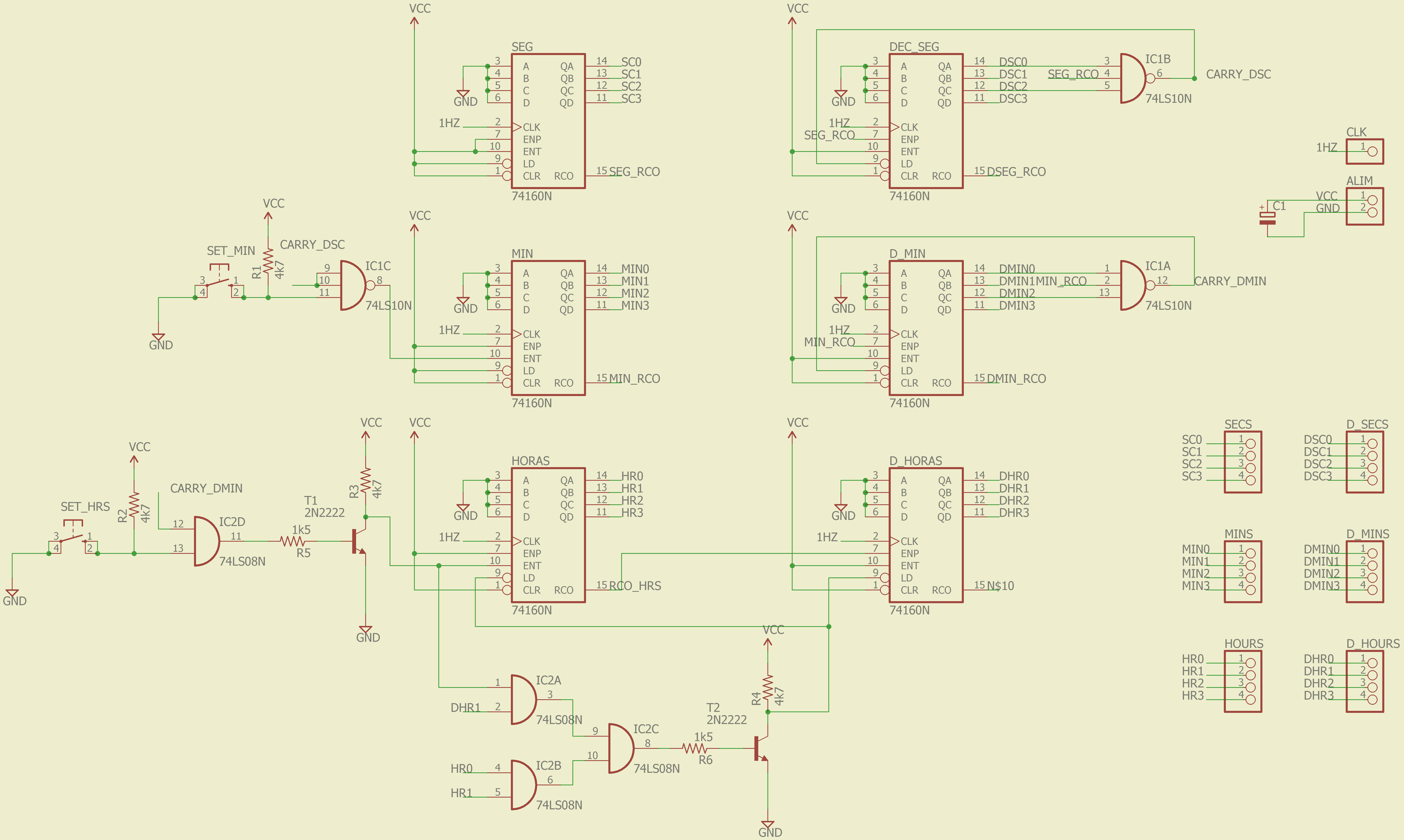
The reason for using AND gates and inverters with a BJT is that when I went to buy the IC's there was only a 74LS10 (3x 3-input NAND) and there were no 4-input ANDs, so I bought a 74LS08 (4x 2-input AND) and I managed with two transistors. Without going into much detail, the count enable of each counter is fed by the overflow of the previous one. Despite being counters with a 4-bit output, being decimals, the overflow occurs automatically in the transition from 9 to 10.
Something funny happened here. I bought more SN74LS160N at Aliexpress in case I got burned some of the ones that I already had. Because the Chinese ones caused the overflow from 15 to 16, instead from 9 to 10. Anyway. So the Aliexpress IC's are only worth me for those I use in dozens of seconds, tens of minutes and dozens of hours, because they are the ones that the overflow is forced to go from 5 to 6 and from 3 to 4, for the tens of hours.
The switches are used to adjust the time, although since the clock of all the counters is 1Hz, the time is set at a rate of 1 second, which is rather impractical. There are two solutions, taking advantage that the frequency divider has outputs of 4, 8 and 32 Hz:
- Do as the Proteus clock and put a counter more than count up to 8 with the 8Hz signal and use its carry for the second counter enable.
- A switch to change the CLK of the clock when you want to adjust the time, although this can produce unwanted peaks and make the clock behave anormally.
This is how the counter PCB looks without soldering:
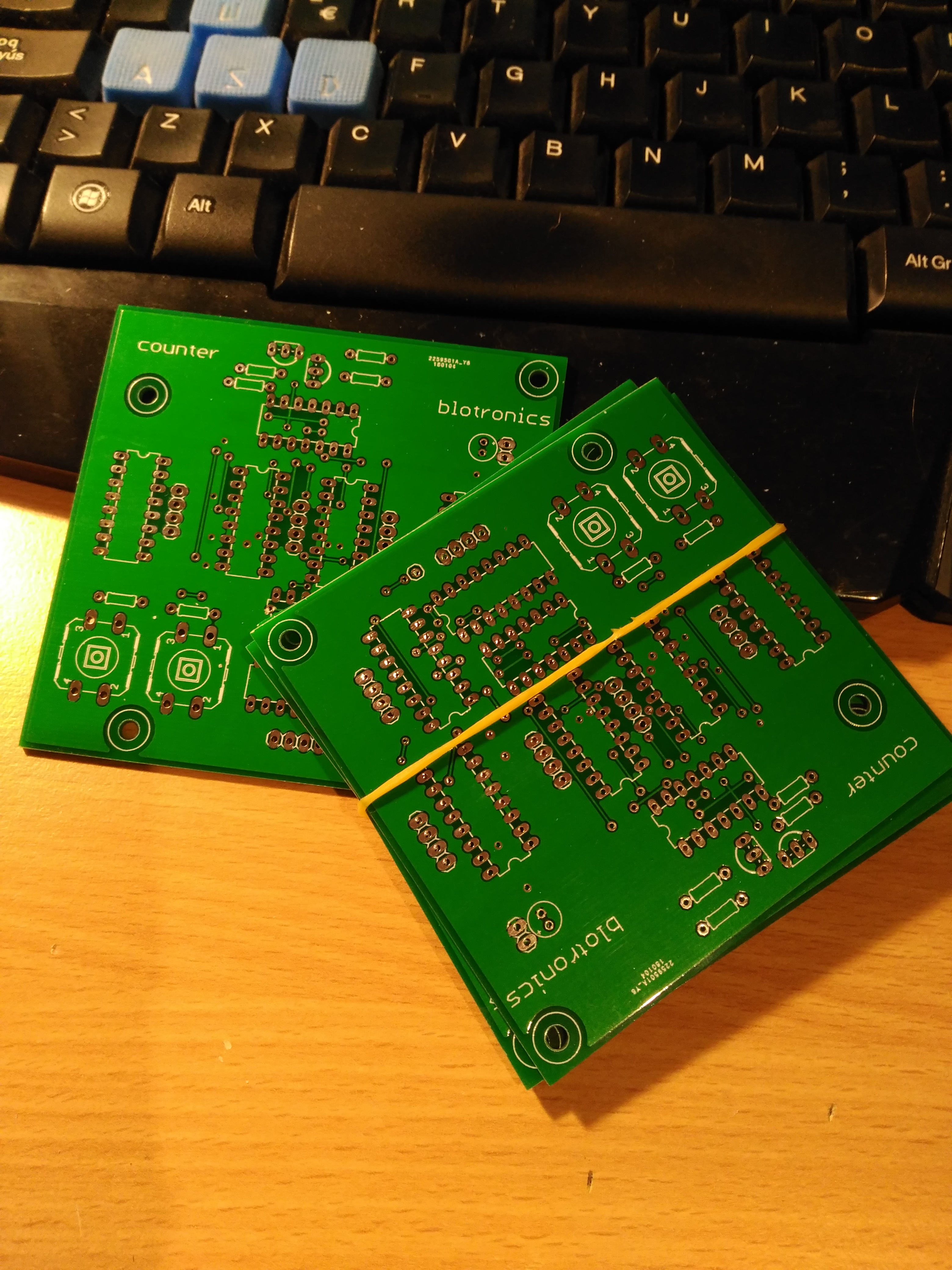 It has been necessary to cut a couple of tracks, things that happen when you dont review old designs.
Here you have the soldered PCB, as you see, I forgot to put the names layer on the gerbers: 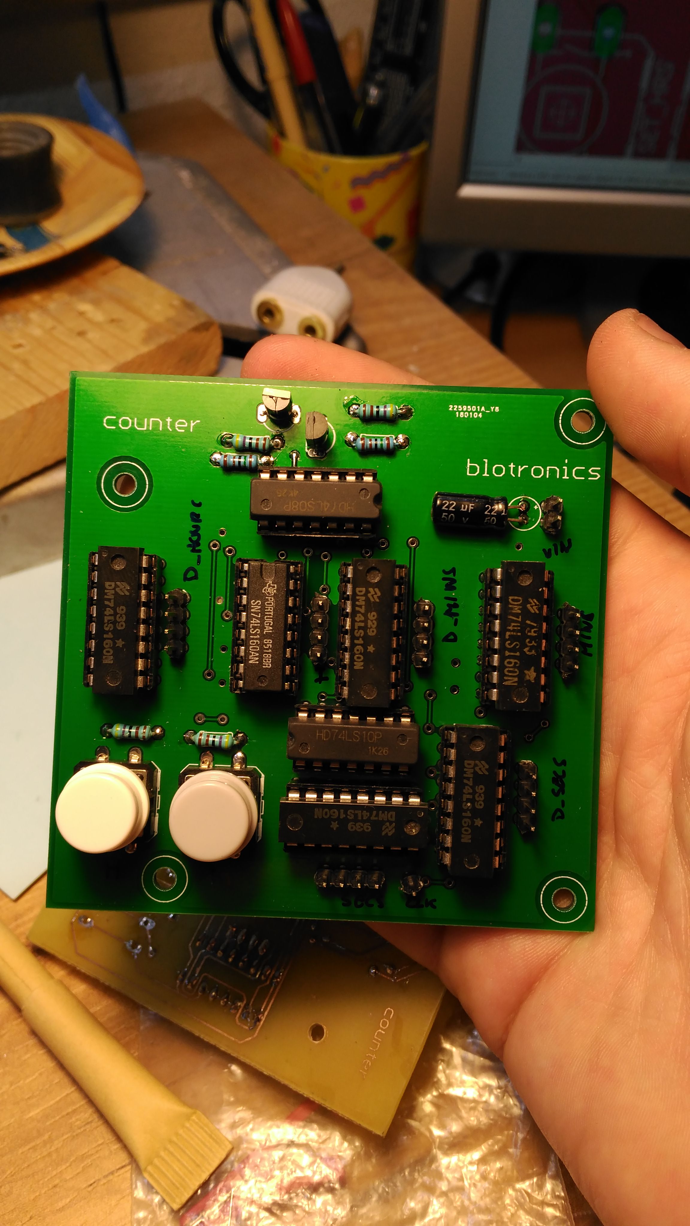
MULTIPLEXOR
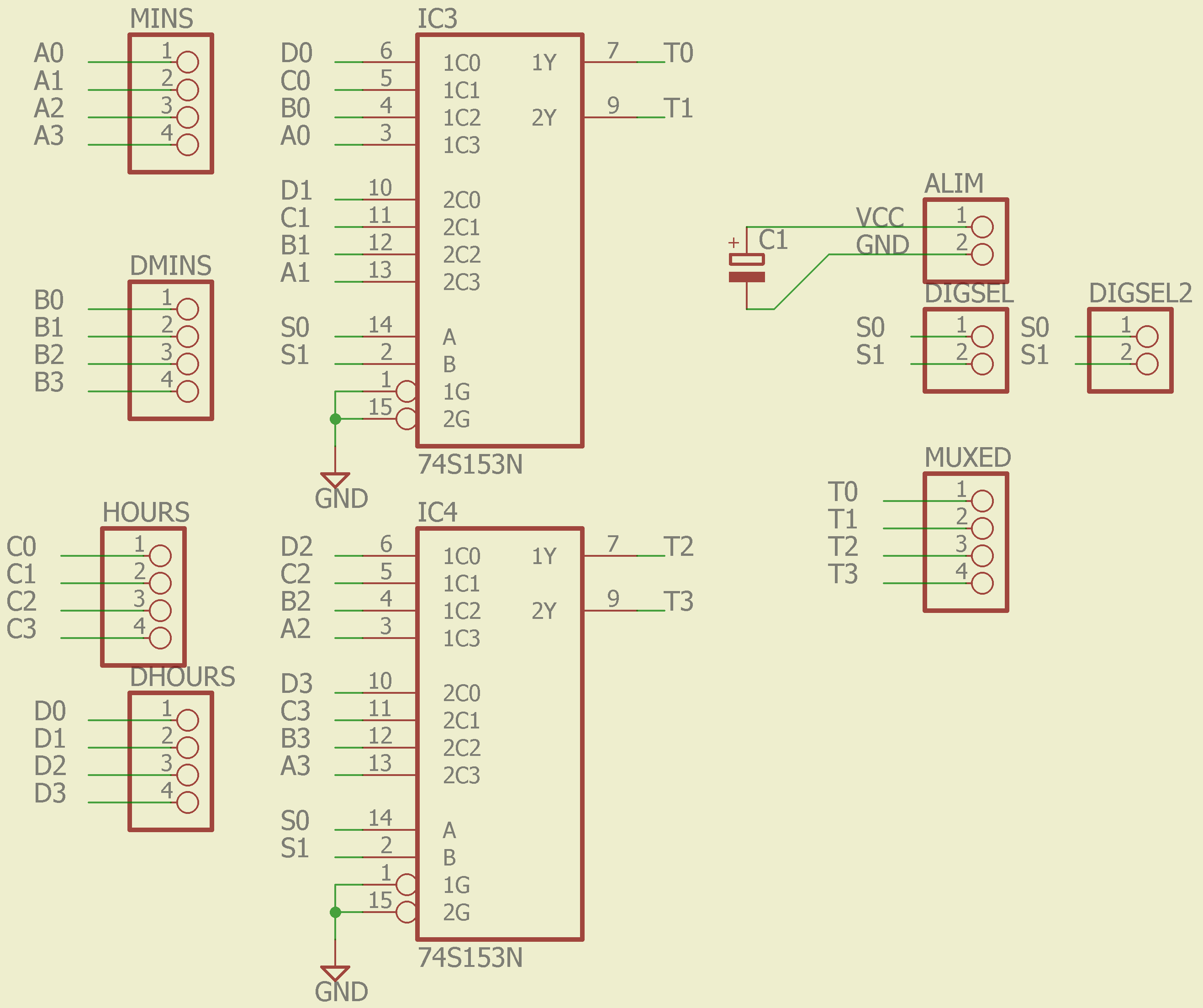
If you remember when I did the Display driver, the display comes only one digit at a time, which is multiplexed with the same signal that I use to decode the display's commons.
The frequency divider outputs a 256Hz signal that goes to a 4-bit counter, which generates 2 signals S0 and S1, at 64Hz and 128Hz respectively. Since four 4-bit buses come out of the counter,I used 2 SN74LS153N (2 x mux 4a1) to multiplex the digits building a 4 to 1 mux for 4-bit buses. See schematic:
 I made this PCB with acid long ago given its simplicity.
DP LOGIC
As I mentioned in the display driver post, I had left the DP pin out to later implement a logic to make it blink every second. Since I have no more 74XX IC's to build the circuit I have used RTL logic (Resistor-Transistor-Logic) because I have enough 2n2222 to stop a train. The function implemented is NAND since the segments are low level logic. This is the circuit:
 Currently this circuit is mounted on breadboard.
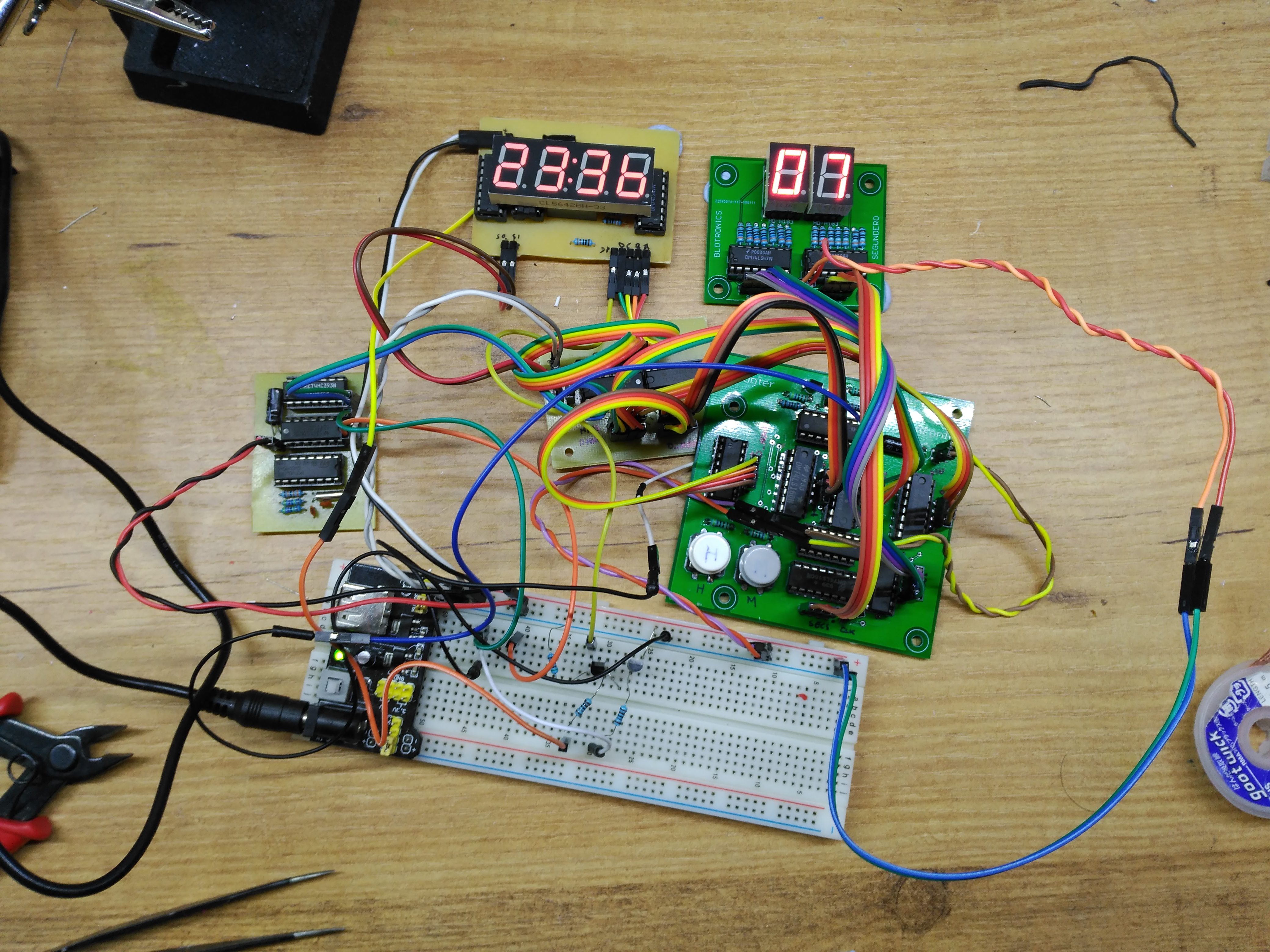
SECONDS COUNTER
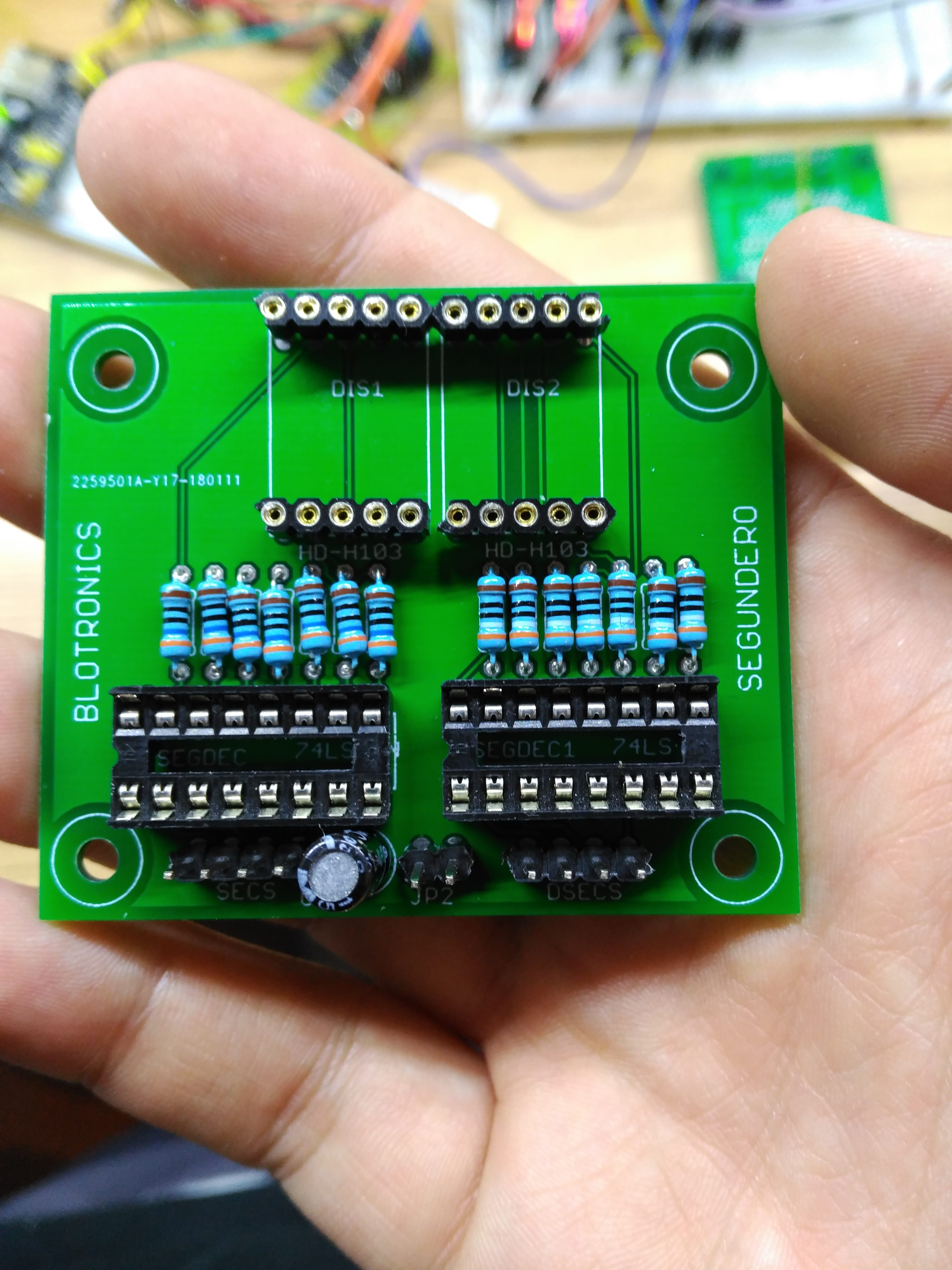
Here you can see the final assembly.
 Here you have a video where you can see the clock working. https://youtu.be/L6TgWI9LYUY Here you have the clock repository: https://github.com/picatostas/digital-clock
What is the next thing I will do with the clock?
Assemble the seconds counter, as the PCB arrives.Blinking logic of the DP.- Solve the clock of the counters to adjust the time faster.
- I ordered PCB for the ones I made with acid and maybe put the muxer on the same PCB with the frequency divider.
- Buy Nixies to make the clock much cooler.
0 Comments