The clocks base their operation on a period of source oscillation. When there were no semiconductors to the clocks, they had to be wound, moved a pendulum or use a crystal oscillator. In this way you got a sustained oscillation which then, in the case of mechanical clocks, was divided into longer times by playing with the gear ratio of a gear train.
Many of the current clocks use a quartz crystal as source of oscillation, material which has a natural tendency to produce a constant frequency oscillation. In the case of an electronic circuit, quartz can be modeled as a capacitor that is periodically discharged and charged. With the help of auxiliary capacitors and a resistor, an RC oscillator circuit can be achieved at a desired frequency.
Having this clear the following question arises, what base frequency is the most appropriate from which to start?

The first thing that can come to mind is to use an NE555 in Astable mode. Who has not ever mounted this integrated with a led to see it blink. But for an application as accurate as a clock, the configuration offered by the NE555 to produce 1Hz and low frequencies in general, is imprecise.
Finally after investigating the clock with nixie tubes (which I do not rule out doing later, it is really cool) I chose this circuit for the frequency divider.
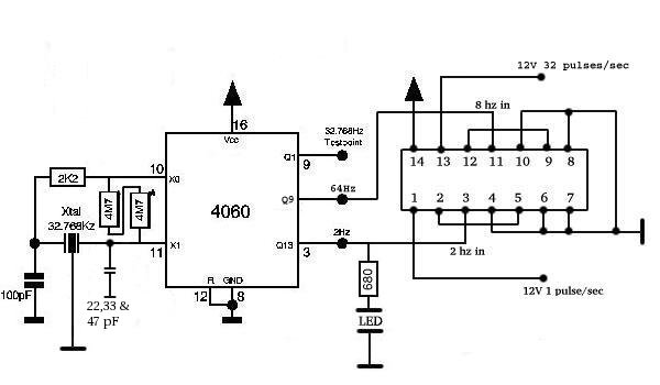
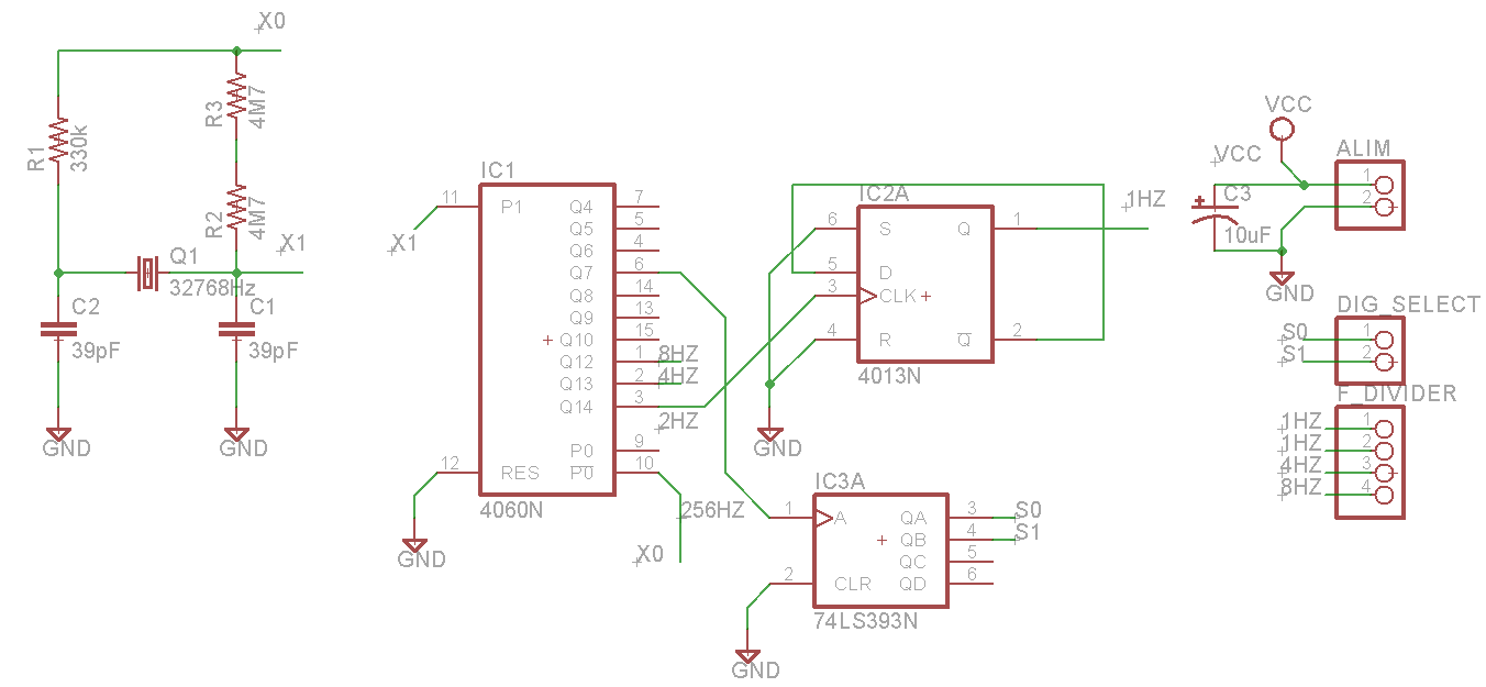
Why use a 32768Hz crystal exactly? Well apart from because it is probably cheap to produce, if we take into account that the frequency division is going to be binary, we will have to look for a starting frequency that when divided by a power of 2 of exact division. This is exactly what happens with 32768Hz, since 2 ^ 15 is 32768. In the case of the chosen circuit, the integrated CD4060 is a 14-bit counter, so one more bit is required to obtain the desired 1Hz frequency for our RTC. That's where the use of the FlipFlop-D comes into play, acting on the last bit.
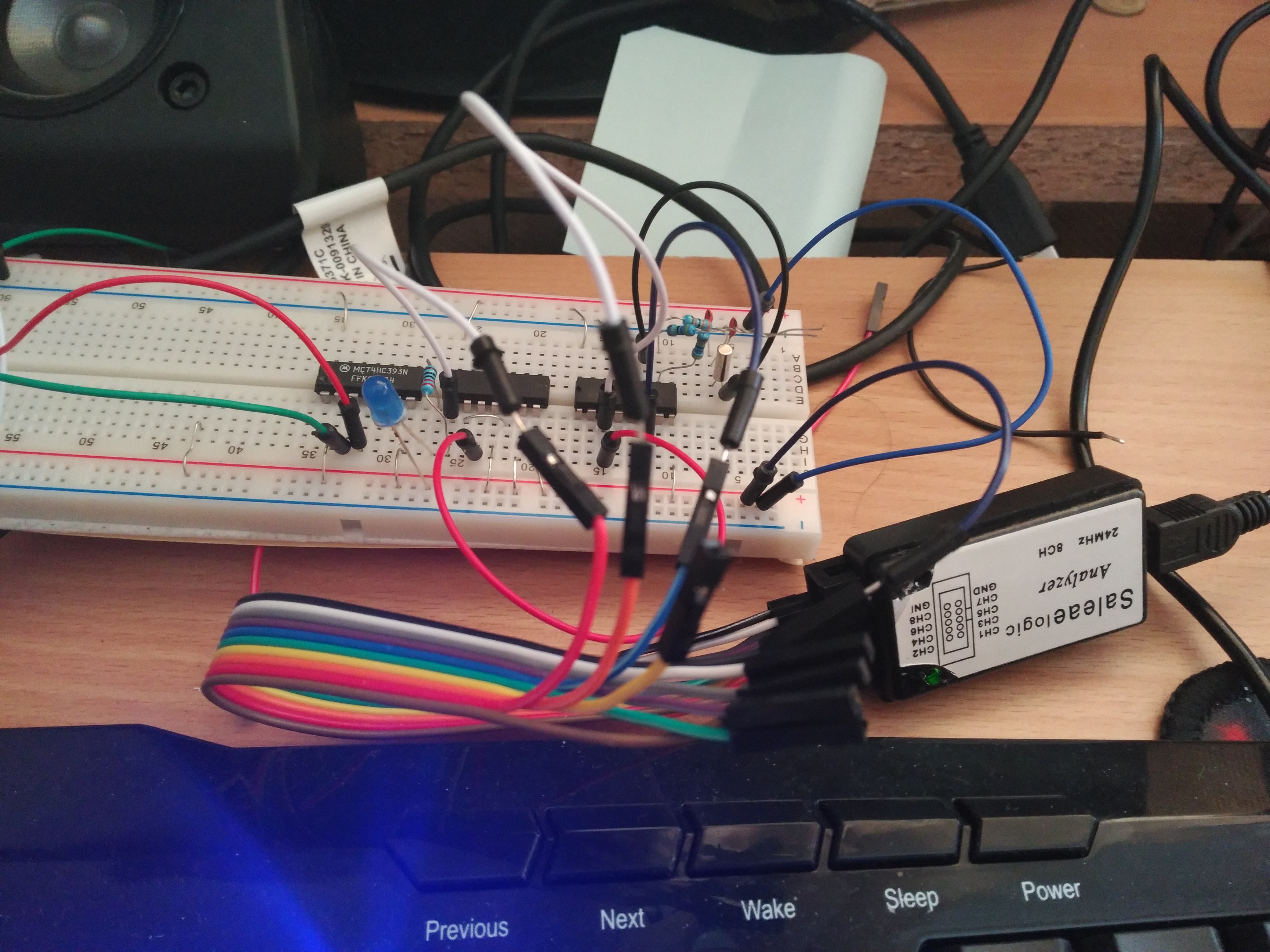
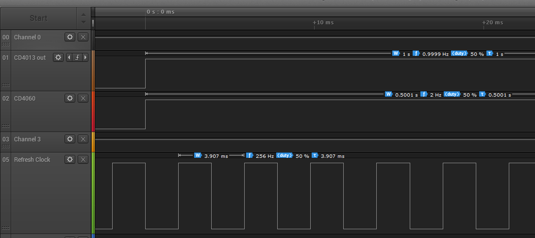
As you can see in the circuit image, the value of the capacities varies for each case, because the components are not ideal. To be able to adjust my circuit, I used a logic analyzer to test capacitors until an optimal value was obtained.
In this photo you can see the data of the generated clock signals, I took out several divisions to make sure that the value of the capacitors was universal and if there was an error, it did not spread excessively in the successive divisions.
Why 256 Hz?
As I mentioned in the driver part of the display, it has common cathodes for the 4-digit segments, and it is the anodes that enable the digit. Which means that to light each digit we have to ground their common. But how do we turn on different numbers for each digit if the segments are common? Multiplexing Turning only one digit, turning off the others, and passing the corresponding number, gets the trick. But how often is the eye deceived so that you do not see how the digits are turned on and off? Well with 50-60Hz per digit, which results in 200-240Hz of "refresh" of the display. Taking advantage of the fact that the CD4060 has the pins of the results of the intermediate frequency divisions between 32768 and 2 Hz, we can use 256Hz to multiplex.
To encode the digit selection I use a 4-bit BCD counter (even if I only use 2) using the 256 Hz CLK. That 2-bit output goes to a decoder from 2 to 4 connected to the common ones of the display. In turn this "bus" of 2 bits will go to the 4 multiplexers that take the value of the corresponding digit. I will explain it in more detail in the next part.
Here are some photos of the final result:

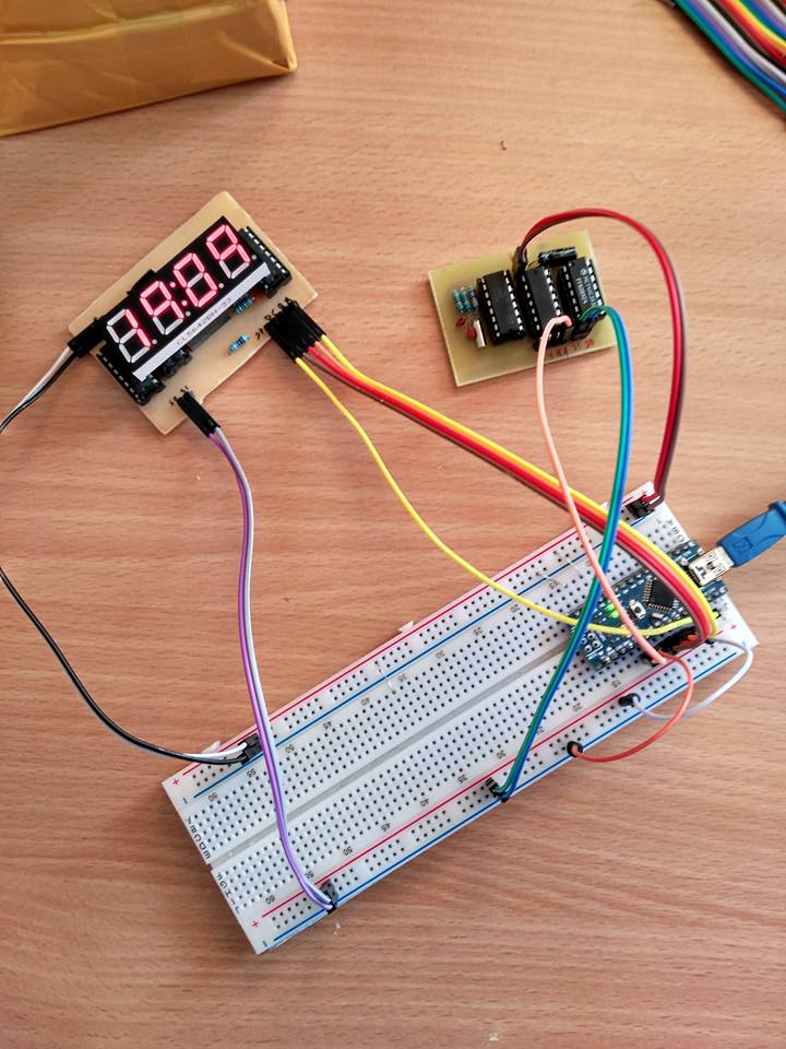 (for the tests as always, Arduino).
Schematic:
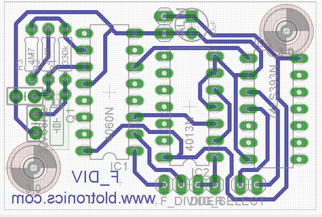
Layout:
 To test the modules I programmed this code:
Here you have the clock repository: https://github.com/picatostas/digital-clock
0 Comments