Since I started with the pedals, I told myself that unless it was strictly necessary and I could not replicate them as it may be the case of the digital processing pedals or those that would constructively cost more, I would do my pedals.
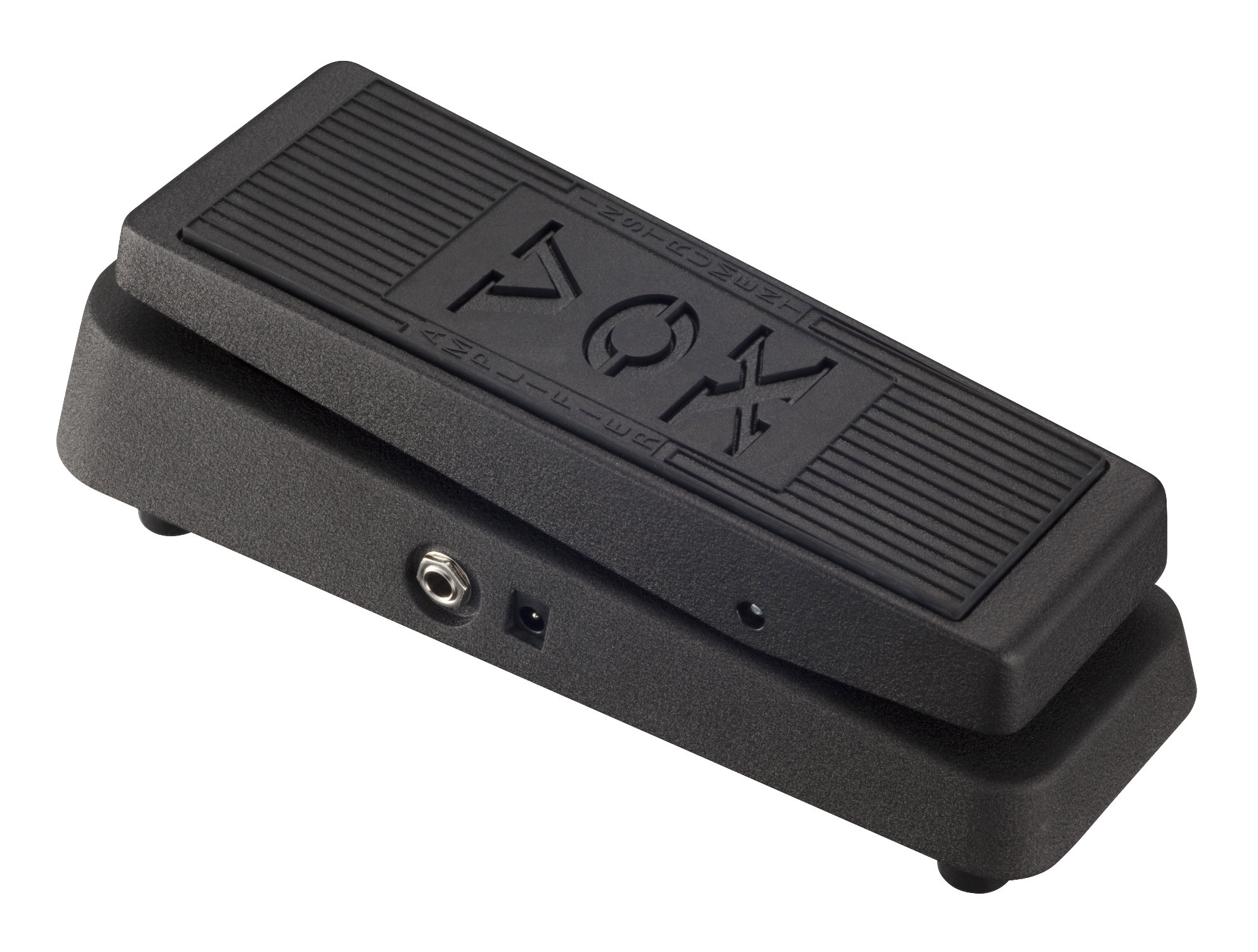
At the time I budgeted to be a Wah, and between boxes, special potentiometer and the inductor, the item was over € 60 and did not compensate me much. So they gave me the VOX V845, the modern VOX Wah, for my birthday.
The truth is that yes, the pedal sounded good, but I did not finish convincing. My pedal, being the "cheap" had no input buffer or TrueBypass so when putting the Wah in the line of pedals, "sucked tone". That is why it did not take a month to make the first mod: the TrueBypass. The great downside of this mod is that the 3PDT that I bought had the shorter shank than the SPDT carling that the original Wahs carry, so the Wah was somewhat hard, later, I removed the tires that damped a little and solved.
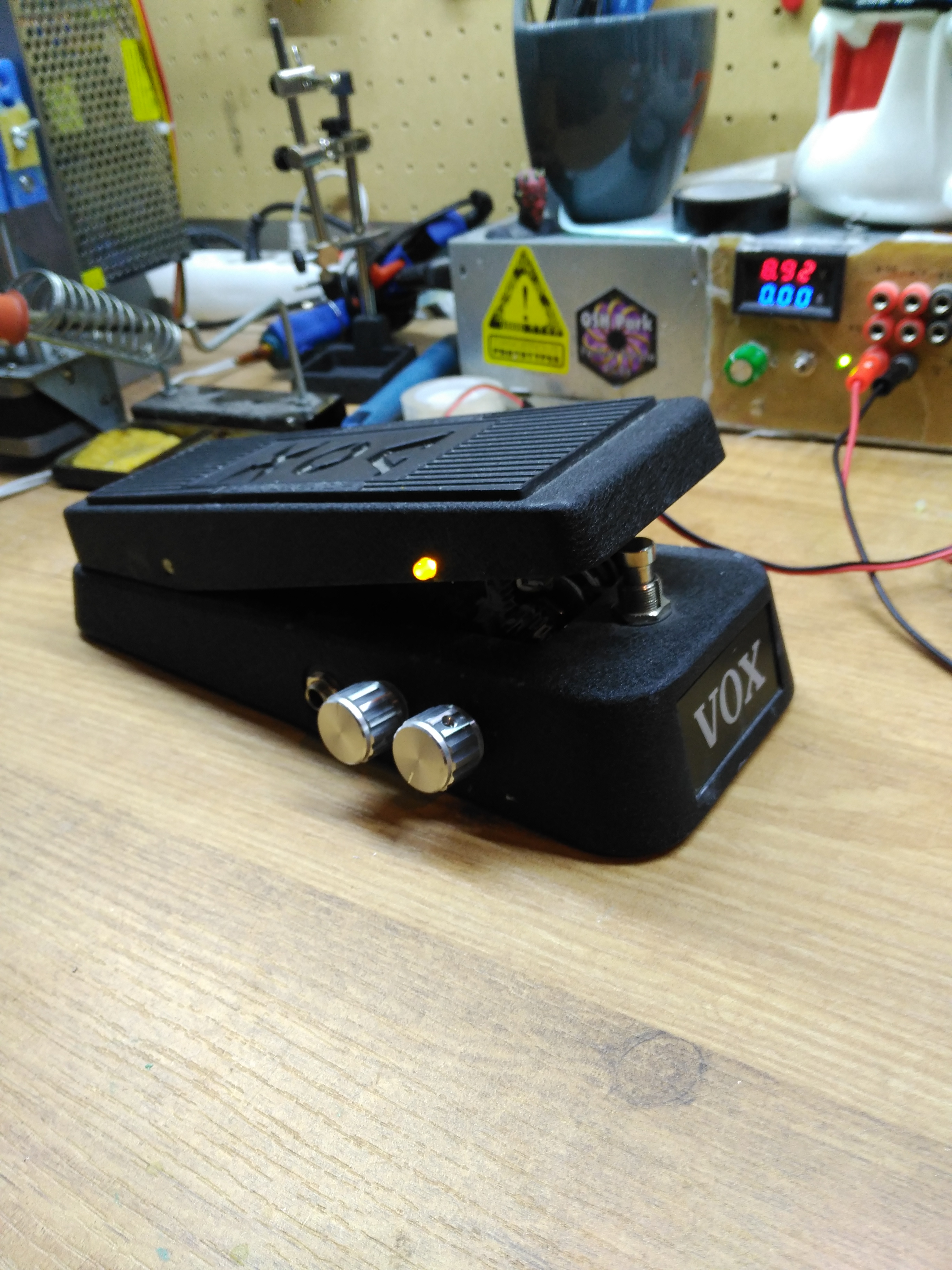
The TrueBypass could have been implemented with a DPDT, but I said, well, since I'm going to put the TrueBypass on it, I buy a 3PDT and I also put a power LED on it. Luckily, in the part that is stepped on the Wah, there was a hole in the edge so I saved myself drilling the box to put the led.
The idea of making me my own Wah has been around my head forever but the truth is that I had never dared. I had seen many articles (FuzzCentral, Instructables, electrosmash, YouTube, etc.) where people reported good and satisfactory results.
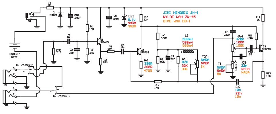
The schematic (updated 2/18/2018) 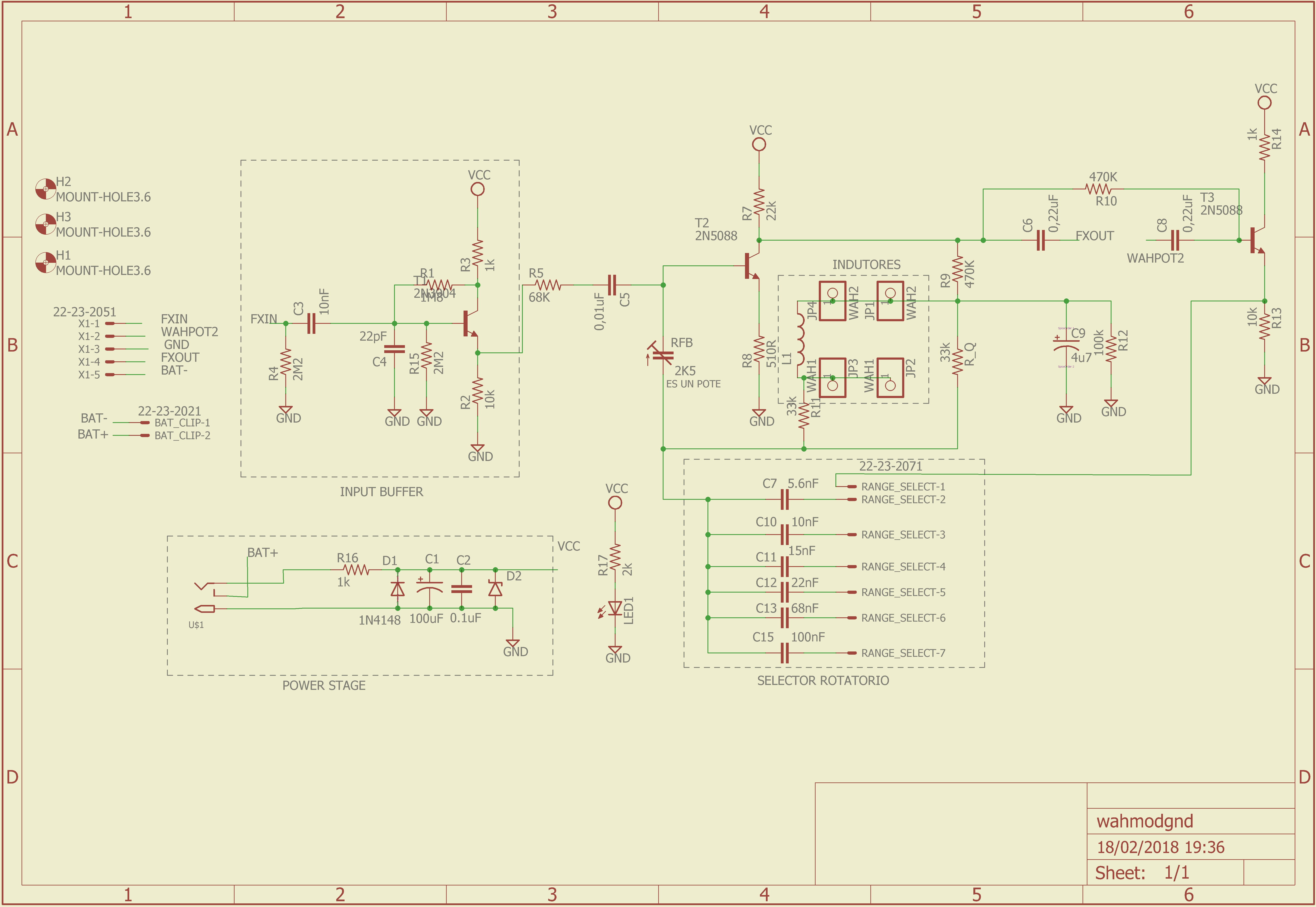
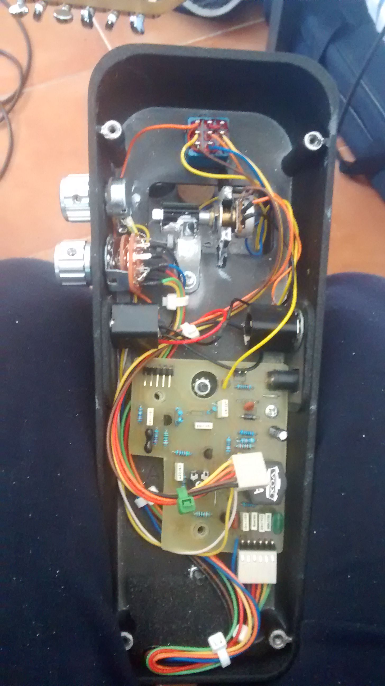
I took measurements of the original plate so that my own fitted and I started to design it. I would have made the mods on the same plate that the Wah came with, but the vast majority of the components, especially the ones I was interested in modifying, were SMD and that complicated the matter a lot.
The circuit that I followed was that of Electrosmash, although it contrasts with the articles of Geofex, FuzzCentral, and some other schematic that I found online, to see how they implemented the different mods.
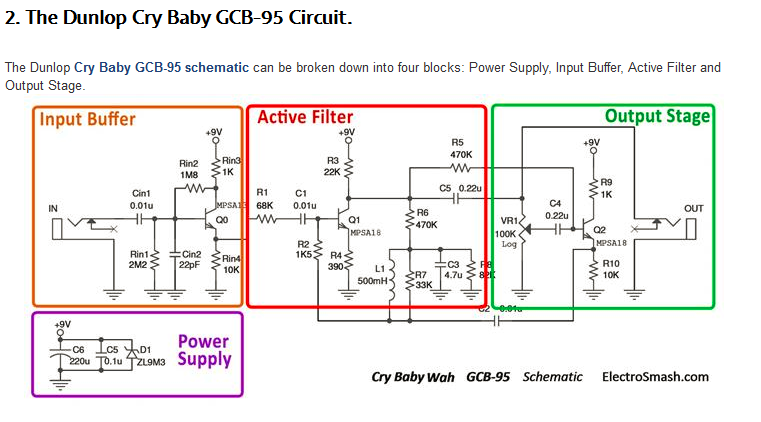
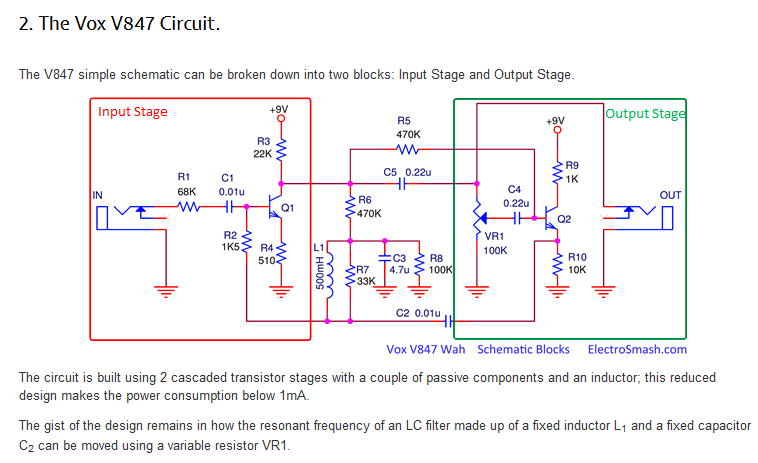 As you can see, there were certain discrepancies on how to implement the Input Buffer; of whether or not to put the resistance of 1k directly feeding the buffer or the entire circuit. That is why on my board I put jumpers to test the different configurations.
The modifications that I put were:
- The input buffer resistance that I mentioned earlier.
- The possibility of putting or not the zener to 9.1V.
- The resistance that is called RFB, its nominal value is 1k5, but with a trimmer of 2k5 you can adjust the amount of media that the signal has.
- The resistance that is in parallel with the inductor. A typical value is 33k but you can see values of up to 100k- I put a 50k potentiometer in series with a resistance of 33k.
- The rotary range selector, changing the value of the capacitor that goes in this part of the circuit, changes the frequency range in which the filter sweep begins when the pedal is pressed.
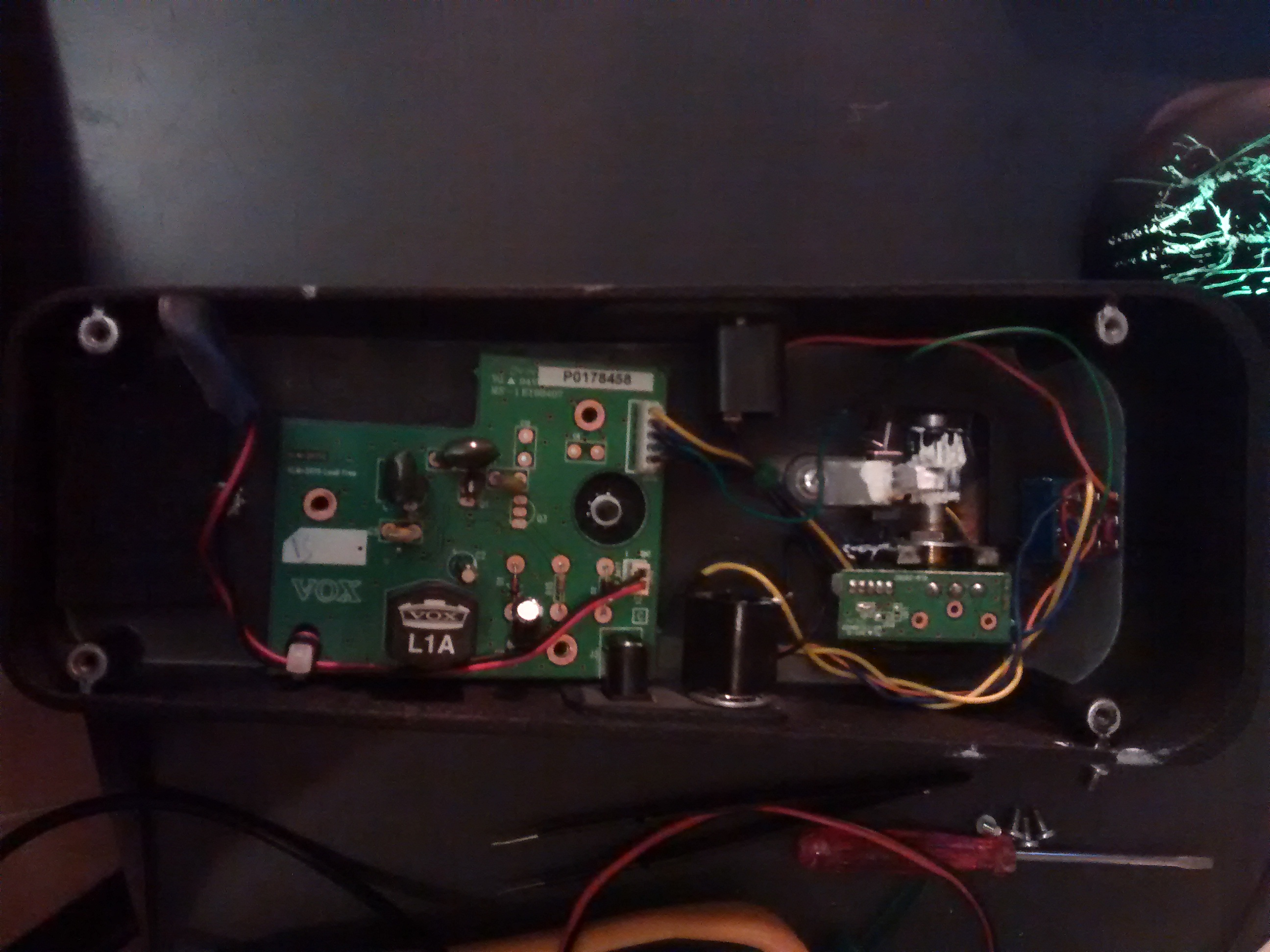
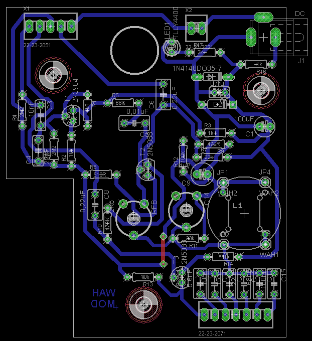
Layout and manufacturing photos: 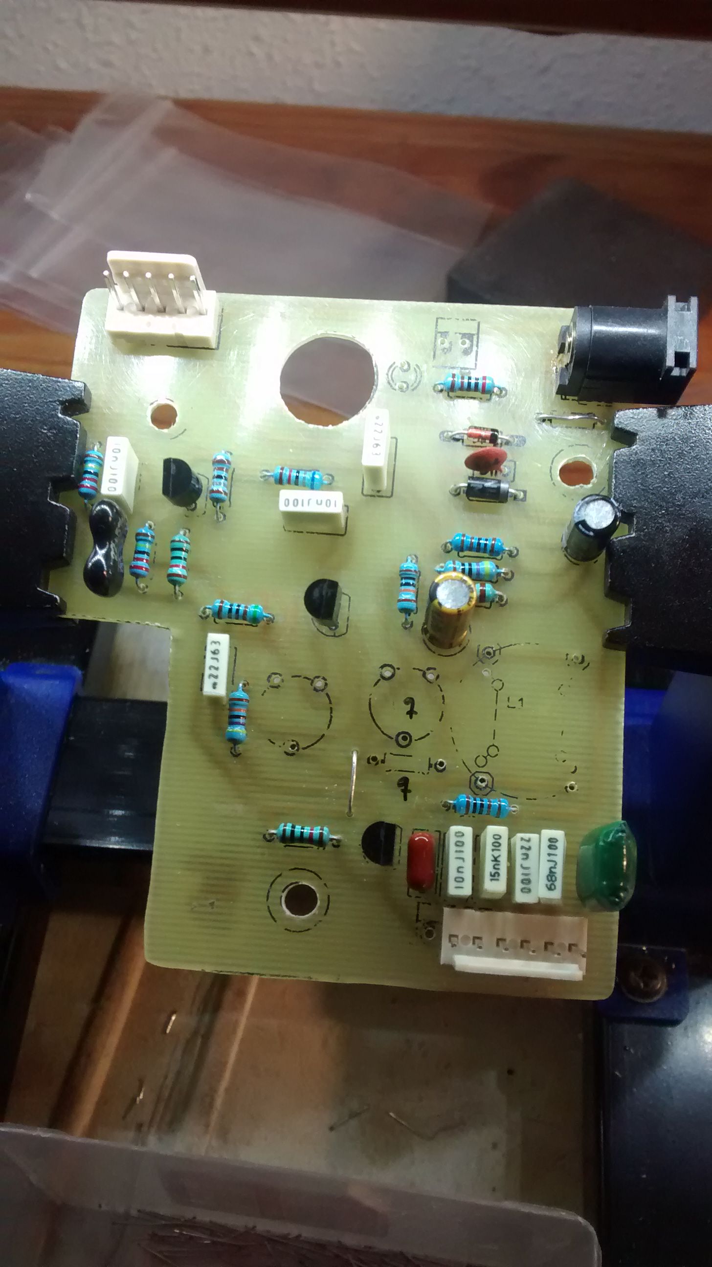
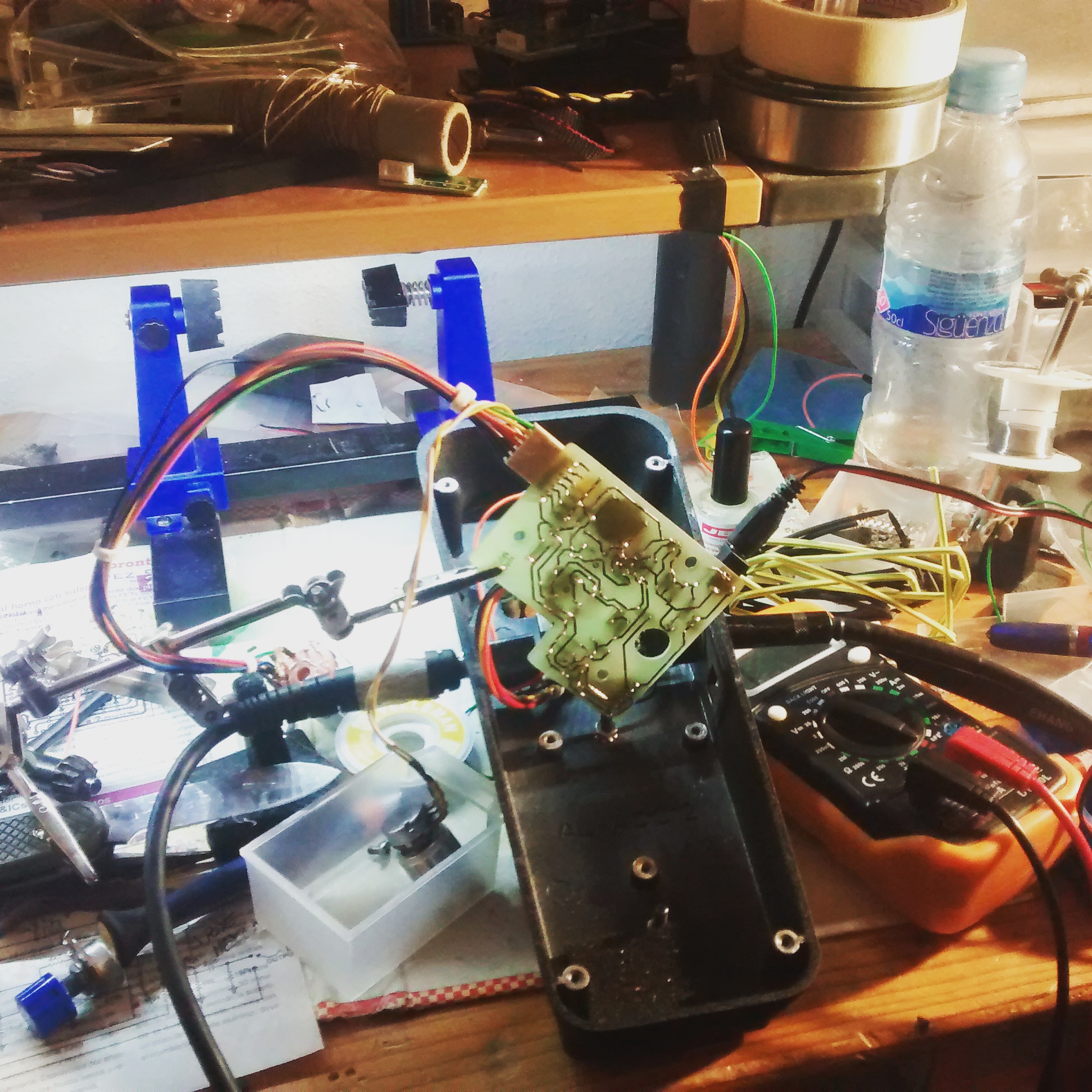
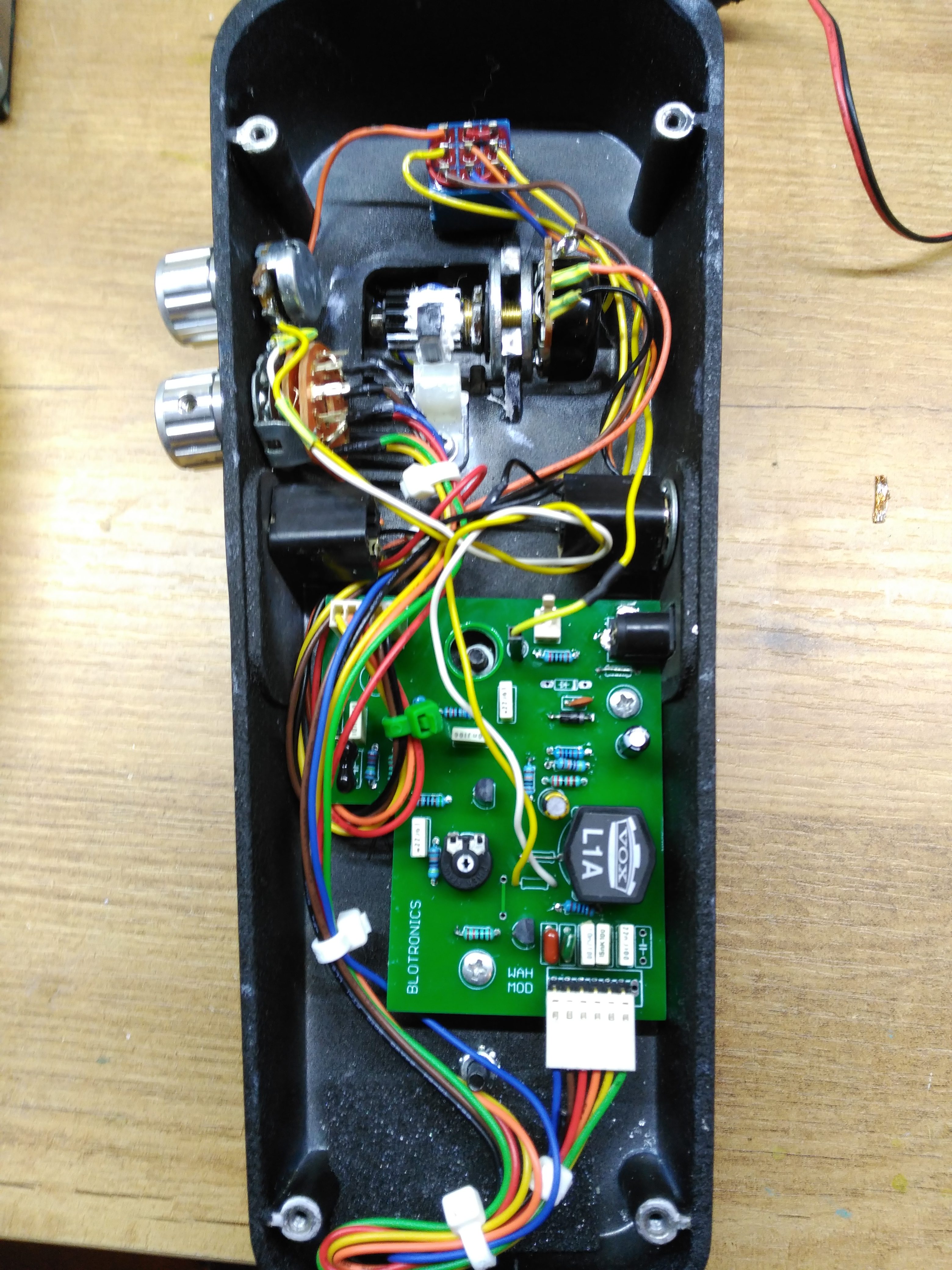
Photos montage:
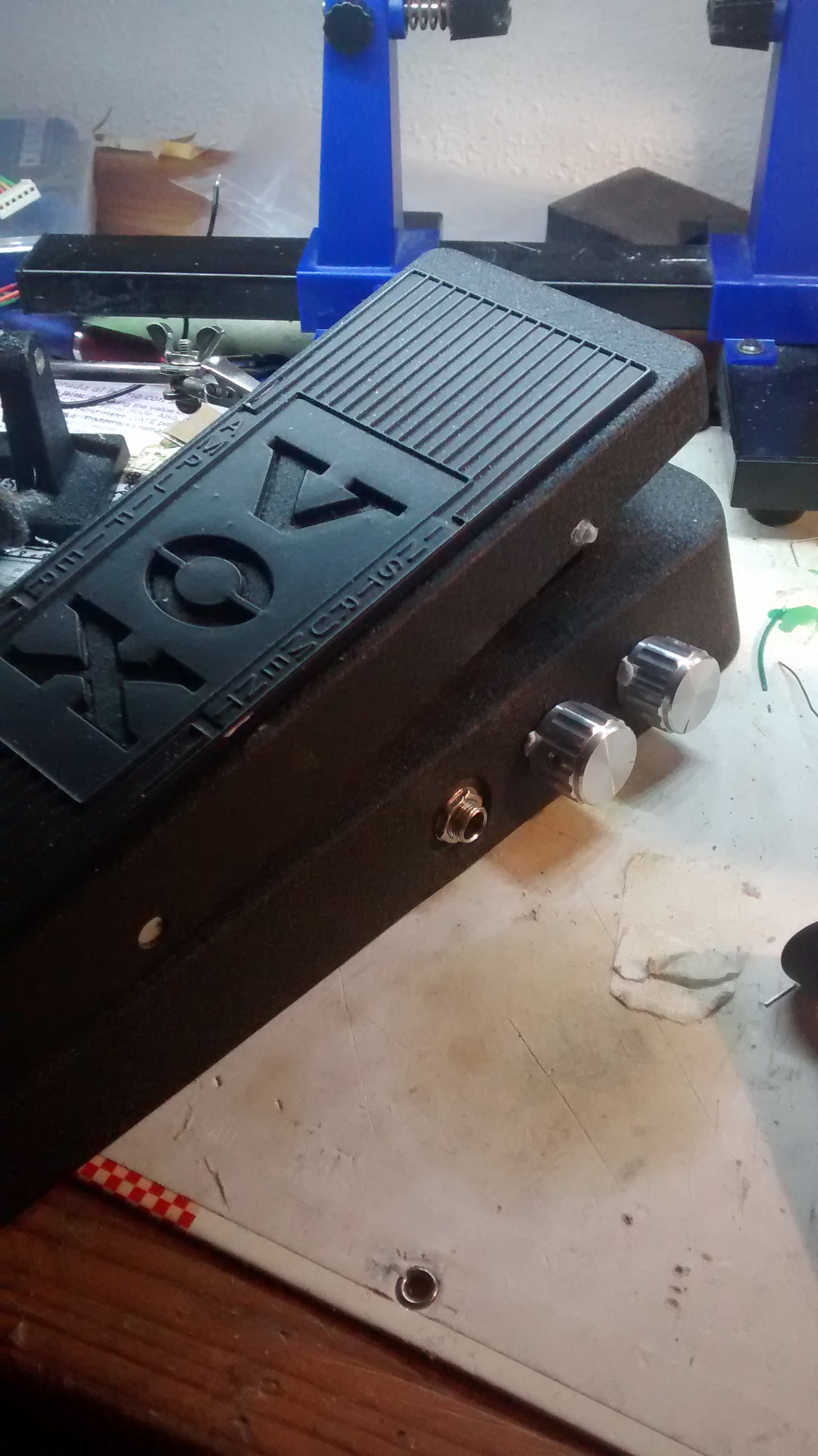
and finally, the finished pedal:
Finally after testing it, I removed the input buffer by simply bridging it on the board, leaving the resistance for TrueBypass pop. I needed an MPSA13 for the buffer but I had already made the order to Musikding, I looked in the stores of Madrid but apparently, you get them from a 2n2222, a 2n3904 or an LM317 and it seems that they do not have more transistors. I bought a BC517 that is the equivalent Darlington, but the electronics dwarf did not want it to work that way.
For the pedal transistors I also had to make changes, instead of putting the MPSA18 (NPF of Hfe ~ 400 and low noise) I used a 2n5088 that I had in the workshop, that although these are noisier they are equivalent in features, I will change them when you make another order for components.
I recycled the potentiometer but I ended up regretting it, as always when you freckle from going cheap, in the end it turns out expensive. I used the one that came with the original Wah and the truth is that it scratches and is of low quality, so in the next order I will buy the ICAR of 100k, which although worth 18 euros, is worth it.
Updated 2/18/2018
I redesigned the circuit because there were things that were wrong, like the buffer, some resistance in parallel that had to be in series and vicecersa, etc.
In my github repository you will find the updated eagle files as well as an Excel with the values according to which variant, however in the photos of the circuits on which I base these values are also.
https://github.com/picatostas/wahwah Finally buy the ICAR pot. This time I ordered the board to JLC PCB. 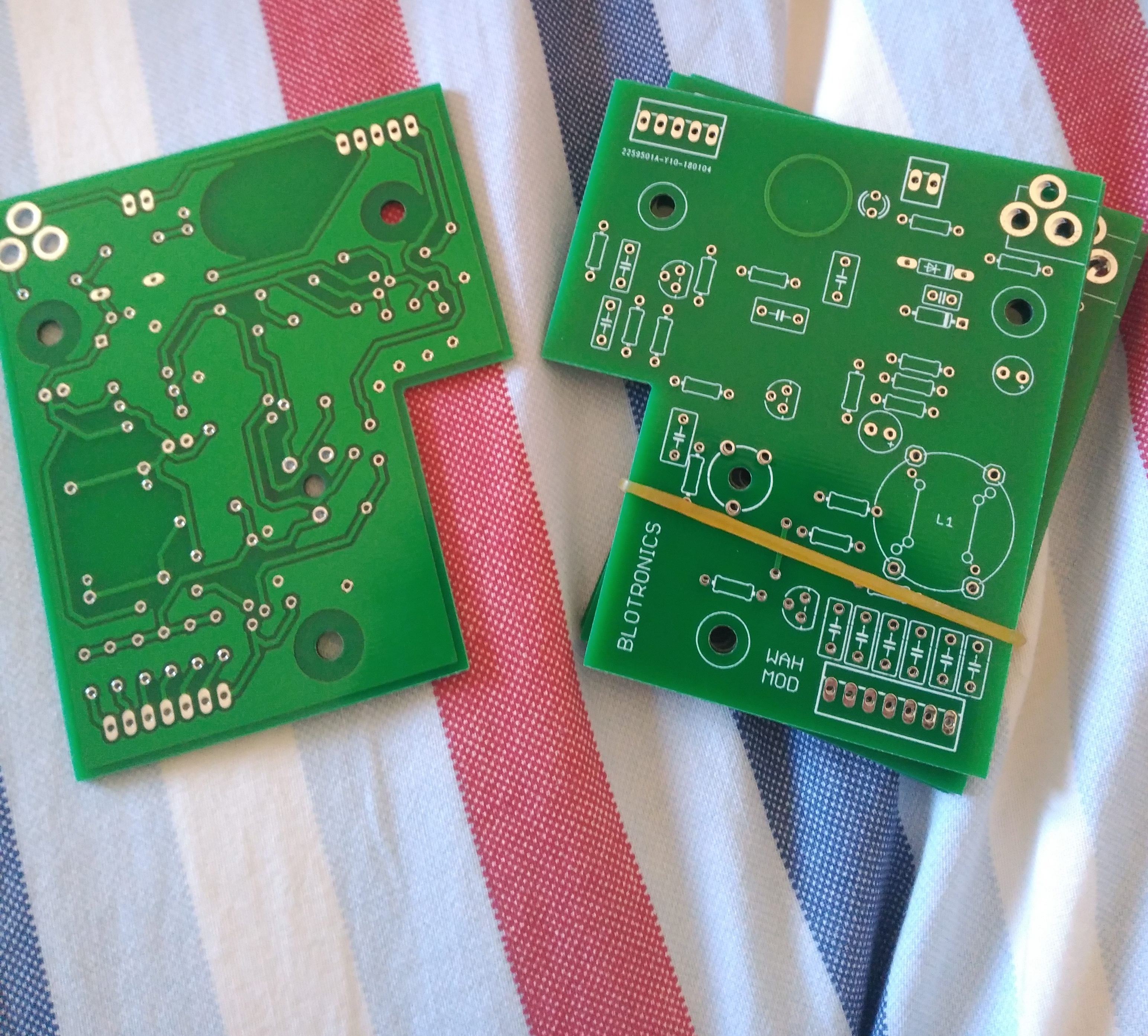 Here you have pictures of the montage.
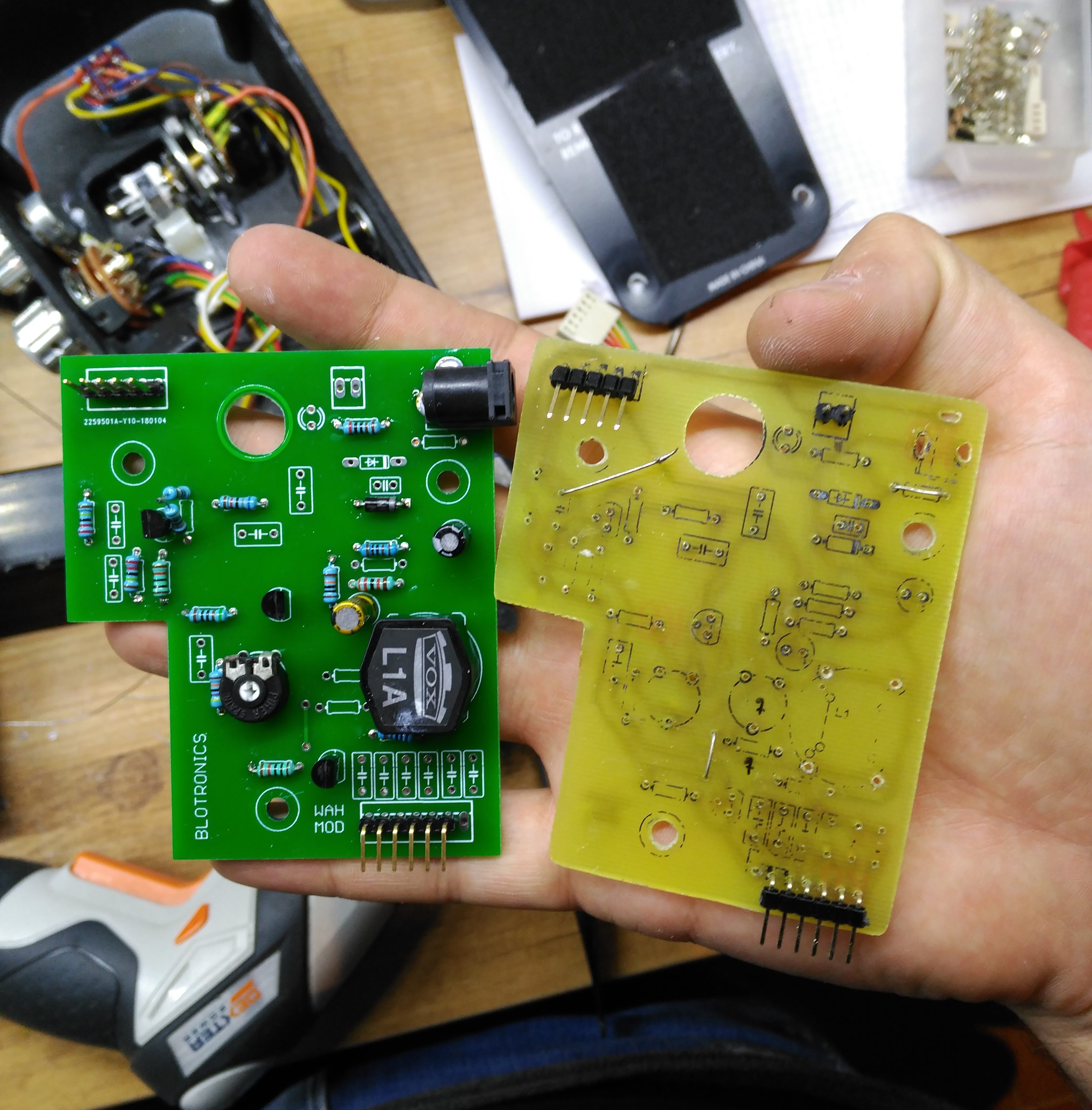
If you liked the article and the result that I have obtained, and you are thinking about doing your foolishness to your pedal, I recommend you to do it because it is very rewarding when you see that it goes well and sounds as you want. I leave the links that I consulted:
Crybaby Electrosmash Vox v847 Electrosmash Analysis Explanation Geofex Article on the similarity of the wah and the human voice FuzzCentral Instructables and this video of CSGuitars https://www.youtube.com/watch?v=lhjNxYqtTvg Sample audio: Sample video: https://www.youtube.com/watch?v=C3Qv1OinNlM
0 Comments