Since the first thing I've done with the display, the first part of the clock I made was its driver.
The display that I used has been a CL5642BH-33. It is a 4-digit display and 7 segments of common anode with double point in between, ideal to make a clock huh This display has a particularity compared to other 4-digit and is that the point for the digit 1 is disabled . Connecting the DP led to the COM1 what turns on is the point of the digit COM2, because the DP + digit COM2 what turns on are the two dots in between.
Being the common anode, the coding logic of the 7 segments has to be at low level and that of digit selection at high level.
- For the 7seg encoding I used a 74LS47N, a BCD-7SEG decoder at a low level, putting a resistance of 330Ω to limit current for each segment.
- For the digit encoding I used a 74LS155N that I had at home, which is a demod / decoder 2-4 at a low level. In principle I was not worthy to need a high level, so I used a 74LS04 to reverse its output. In the first design, the digit driver did it using a PNP inverter stage, but it is true that it is better to use the 74LS04.
- In the case of the DP, since the 74LS47 does not code it to me, I have enabled a pin to later implement a logic so that it blinks every second.
Three buses leave the board:
- Feeding: VCC and GND.
- Selection of digit: S0 and S1.
- 7SEG coding: A, B, C, D and the DP.
The circuit looks like this: and the layout looks like this:
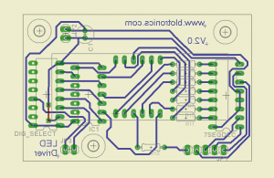 To make the plate I used the LED sunscreen that I built with my friend David. I had not used it for a long time and I had to make some test attempts for the times, even in the last attempt I cut a track, but good, easy to fix.
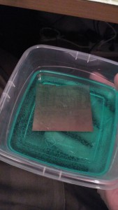
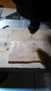
Images of the manufacturing process:
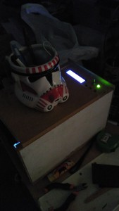
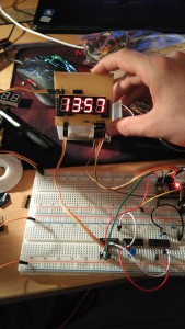
After a while soldering and checking tracks, finally the driver working !!
Here you have the clock repository: https://github.com/picatostas/digital-clock The next part is probably the part of the frequency divider and the clocks.
0 Comments